Quantcast
Channel: IT Network Consulting | Design, Deploy and Support | San Diego
Viewing all 40 articles
Browse latest View live

WAN Design for Multiple Office Connectivity

$
0
0

Businesses with multiple branch office locations often suffer connecting and sharing network resources over the WAN. They tend to think that the WAN technologies are very expensive and more for large enterprises with substantial capital. They didn’t realize that regardless your network size, small or large, the underlying design principles are mostly the same. More often, small businesses leverage cost efficient DSL, 4G LTE, and Internet over Coax cable to provide secondary or backup WAN connections. In this session, we will cover the basic WAN design for multiple office connectivity.

When we do WAN design, there’s a lot of similarities to how we do campus design. If we have a limited number of remote locations, let’s just say we have 500 to a thousand remote sites. We can do just a simple hub and spoke type topology where our main data center is the hub and all of our spokes simply connect directly to that. This can be scaled down all the way to just one HQ and one remote branch.

If we’ve got extremely large networks or they are geographically located, I’ve got maybe a US network, I have a European hub network, and maybe something Asia-Pacific, what I start to do is that I add distribution layers for the WAN in terms of regional aggregation sites per geography. We recommend using a datacenter as the hub site because you’ll need Uninterruptible Power Supply (UPS), cooling and high capacity internet pipes. Tier one and two Internet carriers tend to have presence at major datacenter and colocation facilities. The cost of a high bandwidth circuit is cheaper than what you can get at any office buildings.

 WAN Design for Multiple Office Connectivity

WAN Design for Multiple Office Connectivity (1)

Remote Site WAN Designs

The design methodology for the remote site everything starts from this common basic building block of the single connected remote site- single router, single link. Everything builds based on this foundation. Everyone needs at least one router and one link for a remote site. If I need to add resiliency, one of way of doing that is take the single router and just add another link to it. So, we’ll start with the basic router and then we’ll give you a procedure to add the second link and adjust the routing.

WAN Design for Multiple Office Connectivity (2)

If I want additional resiliency in terms of hardware, now I add a second router, add a second WAN link on that router. On the LAN-facing side, I can do either HSRP or the routing on the LAN side to interconnect the devices. So, we always follow this design principle. I do the basic, I add a link or I add a router with another link. And these can be any different combinations. If you take a look at all the different ways we can do it, the non-redundant single link sites, we can add these single-router dual link sites, we can do dual links with dual routers and all the different transport combinations. Now, we’ve got eight different options here, and then we start adding layer2 links like VPLS or metro services, and 3G/4G. We treat 3G/4G the same way as any traditional physical Internet circuit. We build VPN transport on top of it.

WAN Design for Multiple Office Connectivity (3)

On the LAN side, because a small site may have just a basic access layer, you connect a switch or use an embedded switch in the router module, and we may connect devices right there. That’s a flat access layer connected. We can do the same thing with dual router, and we probably would want to maybe do something with like a switch stack for resiliency and connect the routers to both stack members. We’ve got VLANs for voice and data. When we do dual router, we interconnect them with what we call a transit-net. It’s kind of a link that connects the two routers directly. So, if there’s traffic that needs to go between them, we don’t have to go out the data network.

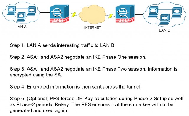
Note that I’m not recommending any traditional static site-to-site VPN tunnels. Newer technology like DMVPN and iWAN allows building encrypted tunnels in a dynamic fashion without the dependency of underlying Internet transport type. The Internet service can be anything offered by the service provider, such as T-1, Metro Ethernet, DSL, 3G and 4G. One of the biggest advantages of DMVPN/iWAN technology is that you are no longer dependent on one service provider to providing IP transit and tunneling services. It used to involve tremendous pain when migrating from one service provider to another.

Remote Site LAN Designs

Let’s take a look at the LAN side. We’ve got recommendations on VLAN assignments and IP schemes and summarization. My general recommendation is as following:

  • VLAN 10: Server Farm
  • VLAN 11: User workstation Dada
  • VLAN 12: User workstation VoIP
  • VLAN 13: Wireless Data
  • VLAN 14: Wireless VoIP
  • VLAN 99: Network transit or the “glue” network designed for router to router communications.

We always want to put VoIP traffic on its own VLAN and subnet for easy routing segmentation and applying QoS policies. Again, these are just the recommendations. VLAN numbers and names are arbitrary. You choose whatever makes sense for your network environment. The key here is that plan for the subnets while taking network summarization into consideration.

WAN Design for Multiple Office Connectivity (4)

For example, we use /21s for all remote sites, so that would give us eight /24 networks to allocate. If you have less than eight remote sites, it makes perfect sense. If you need more or less IP subnetting, we could adjust it. Here I’m just giving you a model that you can start with and scale from there. When we start looking at bigger sites, maybe it’s not just the single building, it’s two buildings. I’ve got multiple access closets, now I need a distribution layer. Your remote site starts looking like a small campus. I’ll give you guides on how to connect to a distribution layer with either a single or a dual router model.

There are primarily three different ways that we could potentially connect our network distribution layer to the WAN Edge. So first of all, they’re all good. They all work and are all widely deployed.

WAN Design for Multiple Office Connectivity (5)

Among these three, option 3 is recommended. There are two reasons this is the recommended design. Number one of which is: because we use a virtual distribution layer, so either we have a switch stack or we have a VSS pair, or we have some highly-resilient modular switch that has multiple supervisors, we have a single control plane at the distribution layer. And then what we do is we use Multichassis EtherChannel and connect two physical links bundled in together for the interconnect from the distribution to the router. The benefit of doing so is that what we have is what looks to be a single logical link. Because of the way it simplifies the control plane and the management in terms of number of devices, and the resiliency it gives us in case we have a link failure.

The key thing to take away is that, at the distribution layer and the WAN Edge, you don’t want to do a lot of static routing (hopefully none). And you don’t want to use first-hop resiliency protocols like HSRP, VRRP, GLBP at the headquarters. We want to use dynamic routing protocols to dynamically learn subnets and network ranges at any location.

Sub-second failover at Core and Distribution layer

Let’s take a look at these two approaches of providing core and aggregation layer redundancy.

WAN Design for Multiple Office Connectivity (6)

Here is just a quick comparison of what I call the routed link failover versus the EtherChannel failover approach. They’re both valid design methods, but the key difference is when we have a failure. If we’re using the routed point-to-point links and had a failure, the routing protocol has to figure out “what changed?”. So, at EIGRP, OSPF, they have to do some sort of recalculation or leverage a feasible successor and then they converge before traffic is flowing again. How long does it take? It depends on the routing protocol. It will be seconds to tens of seconds before the routing table re-converge. VoIP calls will definitely be dropped.

The later model on the right is where we have the virtual distribution layer when we use Multichassis EtherChannel and VSS at the core. When we have a link failure it is only a link within a port channel at layer two. We have a link that’s removed, but at layer three the topology has not changed. At layer three, everything is still the same.

We don’t have to do any route recalculation. All we’ve done is we’ve maybe gone from two one-gig links to a single one-gig link. So, we’ve lost some bandwidth and we have to maybe block all traffic for a short amount of time while we remove that channel member, but this failure is also going to be linear. It doesn’t matter how many prefixes you have in your route table since it’s only a layer two change. The routing didn’t have to change.

On the other hand, the example with the routed point-to-point links, the more prefixes you have in your route table the longer it’s going to take for the convergence to happen. It’ll still happen fast, but we want linearity and predictability, which is another thing we get from doing the Multichassis EtherChannel.

This was just a high level design overview of WAN design for multiple office connectivity. As you can see you have many options to design a low cost while highly redundant branch office WAN connection back to your HQ or datacenter. In the future sessions, we’ll dive into the details on how exactly we configure and manager the network.

The post WAN Design for Multiple Office Connectivity appeared first on Speak Network Solutions, LLC.


What is IPSec VPN PFS Perfect Forward Secrecy

$
0
0

When configuring a IPSec VPN tunnel, it is recommended to enable PFS, or Perfect Forward Secrecy if both side of the VPN devices support the technology. It provides a more secure VPN tunnel. What is IPSec VPN PFS Perfect Forward Secrecy? To understand how PFS works, let’s quickly recap how IPSec tunnel works.

Basic IPSec VPN Tunnel Setup

Phase one

The basic function of Internet Key Exchange (IKE) phase one is to authenticate the VPN peers and setup a secure channel between the peers for further SA (Security Association) exchange in Phase two. Under the hood, it performs an authenticated Diffe-Hellman exchange and making sure the Pre-share Key (PSK) matches. It also negotiates a mutually agreeable IKE SA policy to start IKE exchange.

Phase two

The basic function of IKE phase two is to negotiate IPSec SAs and setup the IPSec tunnel. During phase two, IPSec SAs are established and used to encrypt IP packets sent across the tunnel. The SAs are periodically renegotiated to ensure security.

Post Phase two

After IKE phase two is complete and IPSec SAs are established, information is exchanged by an IPSec tunnel. Packets are encrypted and decrypted using the encryption specified in the IPSec SA.

IPsec VPN PFS Perfect Forward Secrecy

What is IPSec VPN PFS Perfect Forward Secrecy and Why Recommended?

Instead of making use of the DH Keys Calculated during Phase-1, PFS forces DH-Key calculation during Phase-2 Setup as well as Phase-2 periodic Rekey. The PFS ensures that the same key will not be generated and used again.

Think about a scenario that a private key has compromised by a hacker. The hacker would be able to access the data in network transit which is protected by the same key. If we keep using the same key, all future data will be compromised as well. By utilizing PFS, we force the IPSec VPN tunnel to generate and use a different key when it first setup as well as during the periodic rekey. No future data would have been compromised when using a new key.

On a Cisco ASA, if the peer initiates the negotiation and the local configuration specifies PFS, the peer must perform a PFS exchange or the negotiation fails. If the local configuration does not specify a group, the ASA assumes a default of group2. If the local configuration does not specify PFS, it accepts any offer of PFS from the peer. The best practice is to configure all VPN peers with PFS and matching group.

With PFS, every time a new security association (SA) is negotiated, a new Diffie-Hellman exchange occurs, which requires additional processing time. On most modem hardware based VPN appliances the overhead is negligible.

How to configure PFS

Here is an example configuration on Cisco ASA. It forces to use PFS, and IPSec should use the 1536-bit Diffie-Hellman prime modulus group 5 when performing the new Diffie-Hellman exchange.

crypto ipsec transform-set ESP-AES-256-SHA esp-aes-256 esp-sha-hmac
crypto map MyVPN 1 match address VPN-ACL
crypto map MyVPN 1 set pfs group5
crypto map MyVPN 1 set peer 123.123.123.123
crypto map MyVPN 1 set transform-set ESP-AES-256-SHA

Here are differences among Group 1, 2 and 5. Group 5 uses the highest bit DH, and is supposed to be more secure than the others.

Group 1: 768-bit Diffie-Hellman prime modulus
Group 2: 1024-bit Diffie-Hellman prime modulus
Group 5: 1536-bit Diffie-Hellman prime modulus

For full configuration options, please reference the Cisco ASA 5500 Command Line Configuration Guide.

Verify PFS is being used

On a Cisco ASA, issue “show crypto ipsec sa” to verify PFS is being utilized.

inbound esp sas:
spi: 0x492AAFA3 (1227534243)
transform: esp-aes-256 esp-sha-hmac no compression
in use settings ={L2L, Tunnel, PFS Group 5, }
slot: 0, conn_id: 3022848, crypto-map: MyVPN
sa timing: remaining key lifetime (kB/sec): (3914699/25364)
IV size: 16 bytes
replay detection support: Y
Anti replay bitmap:
0xFFFFFFFF 0xFFFFFFFF
outbound esp sas:
spi: 0x879FC1F3 (2275394035)
transform: esp-aes-256 esp-sha-hmac no compression
in use settings ={L2L, Tunnel, PFS Group 5, }
slot: 0, conn_id: 3022848, crypto-map: MyVPN
sa timing: remaining key lifetime (kB/sec): (3908257/25364)
IV size: 16 bytes
replay detection support: Y
Anti replay bitmap:
0x00000000 0x00000001

In this session we covered What is ipsec vpn pfs Perfect Forward Secrecy and why it is recommended for enhanced VPN security. The key takeaway is that if you manage both end of the tunnel, you may enable PFS on both ends. If you are working with a vendor and you do not have control over their VPN configuration, you’ll need to match their settings or disable PFS to bring up a tunnel.

The post What is IPSec VPN PFS Perfect Forward Secrecy appeared first on Speak Network Solutions, LLC.

How to Upgrade SourceFire FirePOWER FireSIGHT Management Center

$
0
0

This information in this article applies to SourceFire 3D appliances, Cisco FirePOWER products and the next generation firewall product family, ASA 5508-X, 5516-X and 5585-X with FirePOWER service enabled. We’ll cover step-by-step process how to upgrade SourceFire FirePOWER FireSIGHT Management Center here.

First you need to find out what software versions your system is running and what new version you are upgrading to. The latest FirePOWER 6.0 has come out with a lot of shinning new features.

However I must caution you against it. Cisco Firepower 6.0 doesn’t support FireSIGHT high availability. This means if you have two managers configured in a HA cluster, you should stay on 5.4 and wait for the 6.01 patch scheduled to be released. Besides it still has a lot of bugs unfixed. At time of this article was written, I upgraded to the latest 5.4.x code train for greatest stability. The general process of upgrading applies to any future code releases as well. Let’s get started and upgrade SourceFire FirePOWER FireSIGHT Management Center.

Most Popular Product Family

Cisco ASA5506-X with FirePOWER integrated

Upgrade SourceFire FirePOWER FireSIGHT Management Center

FirePOWER Appliance 7010

Upgrade SourceFire FirePOWER FireSIGHT Management Center

FirePOWER Appliance 8130

Upgrade SourceFire FirePOWER FireSIGHT Management Center

FirePOWER Appliance 8350
Upgrade SourceFire FirePOWER FireSIGHT Management Center

How to Upgrade SourceFire FirePOWER FireSIGHT Management Center

Before we proceed to upgrade, it is always a good idea to clean up the disk space and make enough room for the new code to be installed. You are probably reading this article because you received a warning message that the disk is getting full. The information here applies to you and you can follow the same instruction to clean up the disk space.

Local backups will not get pruned by the pruning process. They must be deleted by the user manually.

There is feature to configure remote backups, which is recommended. You can configure it by following the instruction at Help > Online

Prune 3D SourceFire FirePOWER Sensor local disk

Patches for old software versions can be deleted. If you are managing the FirePOWER sensors through the FireSIGHT Management Center, formally called Defense Center, you’ll need to login to each sensor and delete the backup files and patches. Go to Devices > Device Management, you’ll find a list of FirePOWER sensor IPs.

Upgrade FirePOWER SourceFire (9)

You can login each individual box by going to https://IP/ .

On 3D Software Version 5.x, navigate to System > Updates, and click the Delete button to the right of any old patches you would like to delete.

  • Local Backups

Backups which have been copied to another device can be safely deleted.

On 3D Software Version 5.x, navigate to System > Tools > Backup/Restore, check any old backup files and click the Delete button.

  • Software Updates

Upgrade FirePOWER SourceFire (1)

Backup SourceFire Defense Center Firepower Management Center

It is always a good idea to obtain a backup of your FirePOWER Management Center (FMC) because all the policies and rules are configured and pushed through the FMC. It is the brain of the whole operation. You can always recover a sensor through the FMC if one ever crashes.

Upgrade SourceFire FirePOWER FireSIGHT Management Center

I covered this topic in greater details here: How to Backup and Restore SourceFire Defense Center Firepower Management Center

Sequential Upgrade is Important

The FireSIGHT Management Center can only manage one version older than the version it is running. If your FirePOWER version was 5.3 or lower, it would no longer be able to manage any FirePOWER sensor 5.4 and greater. Once again, it is important to read the release notes, which states to upgrade all FirePOWER appliances to 5.3 before taking your FMC to 5.4 and newer. To save your time, I have compiled an upgrade path after I’ve read all the lengthy release notes.

  • Step 1: Upgrade FirePOWER sensors to 5.2.0.3, then 5.3.0 then 5.3.0.2
  • Step 2: Upgrade FireSIGHT Management Center (FMC) to 5.3.0.2 then5.3.1 then 5.4.0 then 5.4.1.5
  • Step 3: Upgrade FirePOWER sensors to 5.3.0.2 then 5.4.0 then 5.4.0.6

If you want to go to the latest 6.0.x code, you have two more steps:

  • Step 4: Upgrade FirePOWER sensors to 6.0.0.0 then 6.0.0.1
  • Step 5: Upgrade FireSIGHT Management Center (FMC) to 6.0.0.0 then 6.0.0.1

It is crucial to follow the sequence while upgrade. Failing to do so you may lose the connectivity to the remote sensors or even cause production outage.

Note: If you are upgrading from one major release to another, the “download updates” feature on management console will not pull major releases. You must download the code directly from Cisco.com and upload it through the management console.

Download updates from Cisco.com

To upgrade SourceFire FirePOWER FireSIGHT Management Center, we cannot download different major release updates within the FirePOWER management console itself.  We need to download the files from Cisco.com manually. To download upgrades and patches for the sensors and FirePOWER Management Center, use keyword “FirePOWER” to search for download on Cisco.com/go/support. Find the appropriate downloads to match the product you have.

For the FirePOWER 3D 7110 appliances and the Management Center I have, here are my download options.

Upgrade SourceFire FirePOWER FireSIGHT Management Center Upgrade SourceFire FirePOWER FireSIGHT Management Center

Files downloaded for FirePOWER sensors

Upgrade SourceFire FirePOWER FireSIGHT Management Center

Files downloaded for FirePOWER Management Center

Upgrade SourceFire FirePOWER FireSIGHT Management Center

When I tried to upgrade the Management Center from 5.3.0.2 to 5.4.0, it gave me this error message. I had to download and install the 5.3.1 upgrade package first.

Upgrade SourceFire FirePOWER FireSIGHT Management Center

Please note you need the “Upgrade” package instead of “Patch” when jumping to a different major release.

Start Upgrading FirePOWER sensors and the Management Center

Important: You must follow the correct order mentioned in the previous session. The sequence is important, or you either unable to upgrade or lose connectivity to one or more devices.

Click on install icon in Updates page. If no other issues present, the upgrade will start and you can view the status in the job queue. The device will need to reboot when upgrading to major releases. I witnessed about 30 seconds of network connectivity loss while the sensor reboots, even they are configured “fail-open”. FirePOWER Management Center reboot does not cause network outage.

Upgrade SourceFire FirePOWER FireSIGHT Management Center

The upgrade job will go through file integrity checks, DB verification and etc. The entire process per major release upgrade took me about 30-40 minutes to complete. If you were upgrading to the latest code and have to go through a few intermediate major releases, make sure you plan at least 2 to 4 hours of maintenance window.

If you are using ASDM to upgrade the sensors, the process is the same. You’ll find the UI is the same as well. I recommend upgrading the sensors by going to its own browser based management console directly at https://IP/ The ASDM is just a nice wrapper around it and can add delay and potential issues.

In this session I walked though how to upgrade SourceFire FirePOWER FireSIGHT Management Center and the sensors. As you have seen, the key is to follow the correct order upgrading to one or more intermediate major releases and work towards the final version you want to get to. You cannot jump across major releases.

Continue reading:

Configure and Manage ASA FirePOWER Module using ASDM

Configure and Manage ASA FirePOWER Module using Management Center

How to Backup and Restore FirePOWER Management Center

I have written a quick start guide setting up Cisco’s next-generation ASA-X with FirePOWER service. You can download the configuration template and modify to your needs in matter of minutes.

Cisco ASA 5506-X FirePOWER Configuration Example


The post How to Upgrade SourceFire FirePOWER FireSIGHT Management Center appeared first on Speak Network Solutions, LLC.

How to Backup and Restore FirePOWER Management Center

$
0
0

We’ll walk you through step by step how to backup and restore FirePOWER Management Center, formally called SourceFire FireSIGHT Defense Center.

If you can access the Web UI of the Management Center, it may be possible to create a backup of the configuration and event data so that you can restore to those after re-imaging your DC. Please see the procedures below.

Backup FirePOWER Management Center

Important! If you configured any interface associations with security zones, these associations are not backed up. You must reconfigure them after you restore.

To create a backup file of a Management Center:

Step 1:
Select System > Tools > Backup/Restore.
The Backup Management page appears.

Step 2:
Click on Defense Center Backup. Then Create Backup page appears.

Backup and Restore FirePOWER Management Center

Step 3:
In the Name field, type a name for the backup file. You can use alphanumeric characters, punctuation, and spaces.

Step 4:
On Defense Centers, you have two further options:

  • •To archive the configuration, select Back Up Configuration.
  • •To archive the entire event database, select Back Up Events.
    If the event history is not very important to keep, I recommend uncheck this option by not backing up all the Events.

Step 5:
Optionally, to be notified when the backup is complete, select the Email check box and type your email address in the accompanying text box.

Note! To receive email notifications, you must configure a relay host.

Backup and Restore FirePOWER Management Center (2)

Step 6:
Optionally, on Management Centers, to use secure copy (SCP) to copy the backup archive to a different machine, select the Copy when complete check box, then type the following information in the accompanying text boxes:

  • In the Host field, the hostname or IP address of the machine where you want to copy the backup
  • In the Path field, the path to the directory where you want to copy the backup
  • In the User field, the user name you want to use to log into the remote machine
  • In the Password field, the password for that user name

If you prefer to access your remote machine with an SSH public key instead of a password, you must copy the contents of the SSH Public Key field to the specified user’s authorized_keys file on that machine.

With this option cleared, the system stores temporary files used during the backup on the remote server; temporary files are not stored on the remote server when this option is selected.

It is recommended that you periodically save backups to a remote location so the appliance can be restored in case of system failure.

Step 7:
You have the following options:

  • To save the backup file to the appliance, click Start Backup.
    The backup file is saved in the /var/sf/backup directory. You can direct the backup file to a remote location.
  • To save this configuration as a backup profile that you can use later, click Save As New.

You can modify or delete the backup profile by selecting System > Tools > Backup/Restore, then clicking Backup Profiles. See Creating Backup Profiles for more information. To see the status of a running backup, go to System > Monitoring > Task Status.

Backup and Restore FirePOWER Management Center (3)

Restore FirePOWER Management Center from Backup

You can restore the appliance from backup files using the Backup Management page. To restore a backup, the VDB version in the backup file must match the current VDB version on your appliance.

To restore from a backup, go to System > Tools > Backup/Restore and select the backup file you want to restore from. If your backup is on a remote location, you need to upload the file to the system by clicking Upload Backup first. Click on Restore so the process will start.

Backup and Restore FirePOWER Management Center (4)

After you complete the restoration process, you must apply the latest Rule Update.

If your backup file contains PKI objects, private keys associated with internal CA and internal certificate objects are re-encrypted on upload with a randomly generated key.

If you use local storage, backup files are saved to /var/sf/backup, which is listed with the amount of disk space used in the /var partition at the bottom of the Backup Management page. On Management Centers, select Remote Storage at the top of the Backup Management page to configure remote storage options; then, to enable remote storage, select the Enable Remote Storage for Backups check box on the Backup Management page. If you use remote storage, the protocol, backup system, and backup directory are listed at the bottom of the page.

Backup and Restore FirePOWER Management Center (5)

Step 1:
Select System > Tools > Backup/Restore.
The Backup Management page appears.

Step 2:
To view the contents of a backup file, click the name of the file.
The manifest appears, listing the name of each file, its owner and permissions, and its file size and date.

Step 3:
Click Backup Management to return to the Backup Management page.

Step 4:
Select the backup file that you want to restore and click Restore.
The Restore Backup page appears. Note that if the VDB version in the backup does not match the VDB version currently installed on your appliance, the Restore button is grayed out.

Caution! This procedure overwrites all configuration files.

Step 5:
To restore files, select either or both:

  • •Replace Configuration Data
  • •Restore Event Data

Step 6:
Click Restore to begin the restoration.

The appliance is restored using the backup file you specified.

Step 7:
Reboot the appliance.

Step 8:
Apply the latest Cisco Rule Update to reapply rule updates.

Step 9:
Reapply any access control, intrusion, network discovery, health, and system policies to the restored system.

If you add licenses after a backup has completed, these licenses will not be removed or overwritten if this backup is restored. To prevent a conflict on restore, remove those licenses before restoring the backup, noting where the licenses were used, and add and reconfigure them after restoring the backup.

In this session we covered how to backup and restore FirePOWER Management Center or Defense Center in greater details. It is recommended that you save the backup task in the Backup Profiles and schedule a reoccurring job to run the backup automatically and in certain intervals you feel comfortable with. It can be daily backup, weekly or monthly. It depends on how frequently you change the system configuration and whether you want to back up the events or just the configuration.

Continue reading:

Configure and Manage ASA FirePOWER Module using ASDM

Configure and Manage ASA FirePOWER Module using Management Center

How to Upgrade SourceFire FirePOWER FireSIGHT Management Center

I have written a quick start guide setting up Cisco’s next-generation ASA-X with FirePOWER service. You can download the configuration template for free.

Cisco ASA 5506-X FirePOWER Configuration Example


The post How to Backup and Restore FirePOWER Management Center appeared first on Speak Network Solutions, LLC.

Database Integrity Check Failed on FirePOWER

$
0
0

I have run into the “Database Integrity Check Failed on FirePOWER” issue on the Management Center when I was trying to back up or upgrading the Management Center to a newer version. The fact is that the system will run a DB integrity check before it performs any upgrades or even backup tasks. If the Database integrity check fails, it’ll result in a fatal error like shown below. The Management Center was formally called FireSIGHT Defense Center. They are essentially the same product. I put together my experience and what I did to resolve the issue. Hope it helps you as well.

Update Installation Failed : [ 8%] Fatal error: Error running script 000_start/110_DB_integrity_check.sh

Under System > Monitoring > Task Status

Database integrity check failed on FirePOWER

It is a very common issue when you have a lot of evens coming in and processed by the FirePOWER Management Center. Each event comes in, there is a SQL database table entry created. Over time there are millions of entries being created by the system. Any file integrity error will result in DB check to fail.

The good news is that the corruption most time happens to the Event tables. You can attempt to repair them by running SQL DB repair utilities. Most likely they can be repaired. Worst case if it can’t, you can simply delete the corrupted DB record if the one historical Event isn’t very important to you. I will walk you through the process in a bit.

Database integrity check failed on FirePOWER Management Center

SSH to the FirePOWER Management Center and become Super User

Database integrity check failed on FirePOWER Management Center (2)

Review Log Files to Find Out Where It Failed

In this example I was trying to upgrade my Management Center for version 5.3.0.2 to 5.3.1. I uploaded the file to the Management Center and tried to run the upgrade. I got an error message as below. If you are looking for upgrade instructions, I have one here. ()

Update Installation Failed : [ 8%] Fatal error: Error running script 000_start/110_DB_integrity_check.sh

The FirePOWER Management Center will generate a folder in /var/log/sf/ with the same name of the upgrade or patch you were trying to run. This folder may not be generated if the upgrade process failed in its very early stage. In that case, please skip to the next option. In my case the folder was created here.

/var/log/sf/Sourcefire_3D_Defense_Center_S3_Upgrade-5.3.1

We are looking for DBCheck.log.

Database integrity check failed on FirePOWER Management Center (3)

Open the DBCheck.log file cat ./DBCheck.log. You are looking for the [FATAL] lines, ignore [WARNING]. Here is the output of my DBCheck.log.

OUT: [160316 18:47:43]   FAILED 000_start/110_DB_integrity_check.sh
OUT: [160316 18:47:43]   ====================================
OUT: [160316 18:47:43]     tail -n 10 /var/log/sf/Sourcefire_3D_Defense_Center_S3_Upgrade-5.3.1/000_start/110_DB_integrity_check.sh.log
OUT:
OUT:   rna_flow_stats_1458043200 OK; no repair required
OUT: Processing table rna_flow_stats_1458044400.
OUT: Checking for index file .....found!
OUT: Running mysqlcheck on rna_flow_stats_1458044400
OUT:   rna_flow_stats_1458044400 OK; no repair required
OUT: [Wed Mar 16 18:45:47 2016][FATAL] [table error]             table [rna_flow_stats] loadTableInfoFromDB(): 'SHOW CREATE TABLE rna_flow_stats' Failed, DBD::mysql::st execute failed: Can't find file: 'rna_flow_stats_1455819600' (errno: 2)
OUT: [Wed Mar 16 18:45:47 2016][FATAL] [missing table]           rna_flow_stats
OUT: After Checking DB, Warnings: 14, Fatal Errors: 4
OUT: Database Integriy check produced errors
OUT: Fatal error: ERROR: Database integrity check failed
OUT:
OUT: [160316 18:47:44] Fatal error: Error running script 000_start/110_DB_integrity_check.sh
OUT: [160316 18:47:44] Exiting.
OUT: removed `/tmp/upgrade.lock/UUID'

The output not only revealed the Database integrity check failed on FirePOWER Management Center, it also tells us where it failed at. Looks like we had an issue with table [rna_flow_stats].

If you do not have the log folder and files generated yet because your upgrade process failed in a very early stage, you can review the real-time logs while you attempting to upgrade again.

See real-time update logs:

tail -f /var/log/sf/updates.status

You will see everything the system is trying to do while running the upgrade script. It also includes the outputs as seen in DBCheck.log. Focus on [FATAL] and [FAILED] keywords.

Repair Database Integrity

As we have pin pointed which database table was giving trouble, we can now try to fix the issue. The FirePOWER Management Center comes with a few handle scripts for the exact purpose.

Disable events being transferred

It is always a good idea to temporality disable events being transferred between the sensors and the Management Center while we are trying to work on the database. You don’t want further DB corruptions. Then use the process manager to check all critical services for FirePOWER are running in the background..

pmtool disablebyid SFDataCorrelator
pmtool status | grep -i SFD

You should see the outputs similar to this.

Database integrity check failed on FirePOWER Management Center (4)

Run Database repair script

Here you can run the “repair_table.pl” script against the table where the “DBCheck.pl” script told us. Replace the table name rna_flow_stats with your table name(s) where failed the check.

repair_table.pl -farms rna_flow_stats

The repair script will go through the entire table and its sub-tables and attempt to fix any issue if may find.

Database integrity check failed on FirePOWER Management Center (5)

Chances are, after you ran the repair_table.pl script, it’ll fix all the issues. If it failed to repair all the DB integrity issues, you last option is to drop the table completely. If it was a table for an old event, you may not need to keep it anyway.

mysql -padmin sfsnort -e "DROP TABLE rna_flow_stats_1455819600"

Run DBCheck.pl script again

Once the problematic database table(s) has been repaired, you may run the DBCheck.pl script again and make sure there are no further issues.

Restore events processing

Once we have done our troubleshooting and fixed the issues, remember to re-enable event processing engine.

pmtool enablebyid SFDataCorrelator

Upgrade FirePOWER Management Center

Now we have addressed the database integrity check failed on FirePOWER issue. You may proceed to the system upgrade again. You should be able to apply the upgrade successfully. If it fails for some other reasons, you can go back and follow the same process to troubleshoot. You may find the my other guides useful.

How to Backup and Restore FirePOWER Management Center

How to Upgrade SourceFire FirePOWER FireSIGHT Management Center

Cisco ASA 5506-X FirePOWER Configuration Example

The post Database Integrity Check Failed on FirePOWER appeared first on Speak Network Solutions, LLC.

What is Cisco ACI Fabric

$
0
0

What is Cisco ACI fabric forwarding? The Cisco Application Centric Infrastructure (ACI) allows applications to define the network infrastructure. It is one of the most important aspects in Software Defined Network or SDN. The ACI architecture simplifies, optimizes, and accelerates the entire application deployment life cycle. The network services include routing and switching, QoS, load balancing, security and etc. In this session, I will explain what is Cisco ACI fabric forwarding.

Overview of ACI Fabric

Let’s first understand the basic concepts. Cisco ACI leverages the “Spine” and “Leaf” also known as Clos architecture to deliver network traffic.

The Cisco Application Policy Infrastructure Controller (APIC) API enables applications to directly connect with a secure, shared, high-performance resource pool that includes network, compute, and storage capabilities.

Advantages of Spine and Leaf Architecture

The ACI fabric “Spine and Leaf” architecture offers us a linear scale in both performance and cost’s perspective. With the Spine and Leaf architecture, when you need more servers or device connectivity, you simply add a Leaf. You can add leaves up to the capacity of your Spine. When you need more redundancy or more paths for bandwidth within a fabric, you simply add more Spines.

Cisco ACI Fabric

Basic ACI Fabric Wiring Layout

We typically connect a Leaf to every Spine. A Leaf never connects to another Leaf, as a Spine never connects to another Spine. Everything else in your network connects to one or several Leaves for redundancy and HA.

Within the ACI architecture, there are two different spaces where we are looking at traffic. We have the infrastructure space and the user space. The user space can consist of a single organization, or scaling up to 64,000 tenants or customers from a service provider’s perspective.

Virtual or physical devices such as VM hosts, Firewalls, IPS/IDS appliances, they all connect to the Leaves. We can also connect our external networks. ACI can work with your existing infrastructure. Whatever networks in your existing network, you can connect to the ACI fabric. For example, we connect the Internet and Intranet CE routers to the Leaf layer of the ACI fabric.

What is VxLAN

Inside the ACI infrastructure, we utilize VxLAN, or Virtual Extensible LAN.

In a traditional network, VLANs provide logical segmentation of Layer 2 boundaries or broadcast domains. However, due to the inefficient use of available network links with VLAN use, rigid requirements on device placements in the data center network, and the limited scalability to a maximum 4094 VLANs, using VLANs has become a limiting factor to large enterprise networks and cloud service providers as they build large multitenant data centers.

The Virtual Extensible LAN (VxLAN) has a solution to the data center network challenges posed by traditional VLAN technology. The VxLAN standard provides for the elastic workload placement and higher scalability of Layer2 segmentation that is required by today’s application demands. Compared to traditional VLAN, VxLAN offers the following benefits:

  • Flexible placement of network segments throughout the data center. It provides a solution to extend Layer 2 segments over the underlying shared network infrastructure so that physical location of a network segment becomes irrelevant.
  • Higher scalability to address more Layer 2 segments. VLANs use a 12-bit VLAN ID to address Layer 2 segments, which results in limiting scalability of only 4094 VLANs. VxLAN uses a 24-bit segment ID known as the VxLAN Network Identifier (VNID), which enables up to 16 million VXLAN segments to coexist in the same administrative domain.
  • Layer 3 overlay topology. Better utilization of available network paths in the underlying infrastructure. VLAN uses the Spanning Tree Protocol for loop prevention, which ends up not using half of the network links in a network by blocking redundant paths. In contrast, VxLAN packets are transferred through the underlying network based on its Layer 3 header and can take complete advantage of Layer 3 routing, equal-cost multipath (ECMP) routing, and link aggregation protocols to use all available paths.

You can read more about VxLAN technology here: VXLAN Overview: Cisco Nexus 9000 Series Switches

Traffic Flow in ACI Fabric

User traffic is encapsulated from the user space into VxLAN and use the VxLAN overlay to provide layer 2 adjacency when need to. So we can emulate the layer 2 connectivity while providing the extensibility of VxLAN for scalability and flexibility.

When traffic comes in to the infrastructure from the user space, that traffic can be untagged frames, 802.1Q trunk, VxLAN or NVGRE. We want to take any of this traffic and normalize them when entering into the ACI fabric. When traffic is received from a host at the Leaf, we translate the frames to VxLAN and transport to the destination on the fabric. For instance we can transport Hyper-V servers using Microsoft NVGRE. We take the NVGRE frames and encapsulate with VxLAN and send to their destination Leaf. We can do it between any VM hypervisor workload and physical devices, whether they are physical bare metal servers or physical appliances providing layer 3 to 7 services. So the ACI fabric gives us the ability to completely normalize traffic coming from one Leaf and send to another (it can be on the same Leaf). When the frames exit the destination Leaf, they are re-encapsulated to whatever the destination network is asking for. It can be formatted to untagged frames, 802.1Q truck, VxLAN or NVGRE. The ACI fabric is doing the encapsulation, de-capsulation and re-encapsulation in line rate. The fabric is not only providing layer 3 routing within the fabric for packets to move around, it is also providing external routing to reach the Internet and Intranet routers.

  • All traffic within the ACI Fabric is encapsulated with an extended VxLAN header along with its VTEP, VxLAN Tunnel End Point.
  • User space VLAN, VxLAN, NVGRE tags are mapped at the Leaf ingress point with a Fabric internal VxLAN. Note here the Fabric internal VxLAN acts like a wrapper around whatever frame formats coming in.
  • Routing and forwarding are done at the Spine level, often utilizes MP-BGP.
  • User space identities are localized to the Leaf or Leaf Port, allowing re-user and/or translation if required.

What is Cisco ACI Fabric

When we look at connecting the existing datacenter networks into ACI, what we do is accepting either typical subnets on any given VRF or a VLAN for any given device externally. We then translate them into the ACI fabric as external entities or groups that could be in parts of the Application Centric Infrastructure that we use building out the logical model.

Location Independent

VxLAN not only eliminates Spanning Tree Protocol, it also allows us to have location independent within the fabric. The IP address itself is intended to identify a device for forwarding purpose. Within the ACI fabric, we take a device IP and map it to a VxLAN ID or VNID. It helps us to identify where the packet is located at any given time. What it means is that with any virtual machine host, it is identified by an IP address within that server and the VNID at the ACI Leaf. If this host were to migrate to a VM hypervisor at a different location within our ACI fabric, its VNID is replaced by the destination Leaf’s VNID and forwarded over. Now the ACI fabric knows that the VM with the same IP is the same host, simply relocated to a different location. This allows us to provide very robust forwarding to a device while still maintain the flexibility provided by workload mobility. This gives us a very robust ACI fabric, extremely scalable, and allows us to provide mobility within user space across the infrastructure space at any given end point.

What is Cisco ACI Fabric

In the diagram above, let’s say we are migrating VM1 from the server farm on the right to the left. These steps are followed:

  • Step 1: VM1 is sent to the Leaf where it is directly connected. The frames are normalized and encapsulating into VxLAN format.
  • Step 2: VM1 is identified by its IP address within the server and the VxLAN Network Identifier (VNID) of the Leaf it is sitting on right now. The Leaf is then forward the packet to the Spine for forwarding decision making.
  • Step 3: The Spine router replaces its VNID with the destination Leaf’s VNID and sends it over.
  • Step 4: The destination Leaf receives the packets and strips off the VxLAN wrapper then forward to the new server farm. From the network’s perspective VM1 is still the same host with the same IP address.

ACI Fabric Scalability

The scalability of the fabric is based on the Spine and Leaf design. With this design, we get a linear scale from both performance and cost perspective. It is a cost-effective approach as we grow the network. A network can be as small as less than hundred ports to up to a hundred thousand 10G ports and million end points.

The post What is Cisco ACI Fabric appeared first on Speak Network Solutions, LLC.

Converting Cisco Wireless Access Point from Lightweight Mode to Autonomous Mode and Vice Versa

$
0
0

Whether a Cisco wireless access point (AP) was pulled from production or purchased new, it comes in one of the two operating mode: Lightweight or Autonomous Mode. When you are deploying the AP on your network, you must decide what mode you want to run. The decision is fairly easy. If you are dealing with a single location, a small office or home network, autonomous mode is recommended. If you are setting up a wireless network for a larger office space that requires more than 3 access points locally or remotely across multiple geographic locations, deploying in Lightweight mode is recommended. In this session we’ll explain converting Cisco Wireless Access Point Lightweight mode Autonomous mode.

Converting Cisco Wireless Access Point from Lightweight Mode to Autonomous Mode

Lightweight (LWAPP) Mode vs. Autonomous Mode

First of all let’s put all the terms together-

Lightweight (LWAPP) Mode: Centrally managed by a Wireless LAN Controller or WLC. The WLC can be a physical appliance for large networks or it can be a virtual machine. Sometimes it is embedded into ISR router or a switch such as Cat3850. Cisco calls it “Converged Access”. The “brain” is at the controller level. Think of the AP is simply an Ethernet extension transmitting data frames between wire and wireless. The controller tells the AP who to transmit to and what to transmit and all added on security, OoS and so on.

Autonomous Mode: Also known as Standalone Mode. The AP itself is in charge of all the operations such as managing SSIDs, security, client authentication, even DHCP and DNS. All services are self-contained and individually managed by each AP.

What about CAPWAP?

CAPWAP, based on LWAPP, is a standard interoperable protocol that enables a controller to manage a collection of wireless access points.

LWAPP was invented in 2001 as a mean for an AP and a controller to exchange control and data, by a company called Airespace. When Cisco acquired Airespace in 2005, they sponsored an effort to standardized this protocol. LWAPP was offered as a basis to a something IETF already working on called Control and Provisioning of Access Points (CAPWAP). After about 2 years of re-crafting, the slightly modified and improved, CAPWAP protocol came out, intended as being an RCC, therefore available to anyone. Cisco integrated CAPWAP into their solution.

Today, all Cisco controllers (and APs) use CAPWAP, but controllers can still recognize LWAPP requests and push to the matching AP a firmware that contains CAPWAP, so that the AP can join the controller successfully.

You can deploy CAPWAP controllers and LWAPP controllers on the same network. The CAPWAP-enabled software allows access points to join either a controller running CAPWAP or LWAPP. The only exceptions are that the Cisco Aironet 1040, 1140, 1260, 3500, and 3600 Series Access Points, which support only CAPWAP and join only controllers that run CAPWAP. For example, an 1130 series access point can join a controller running either CAPWAP or LWAPP where an1140 series access point can join only a controller that runs CAPWAP. Got confused? My recommendation is that always upgrade the code to a recent software release and it most likely will work in your environment. Unless you are running really old hardware, you’ll be fine in most cases.

How can you tell if an AP is running in Lightweight mode or Autonomous mode?

There are a few signs you can find to determine whether your AP was configured in Lightweight or Autonomous mode.

Autonomous APs have in their image name: K9W7 while Lightweight APs have K9W8. You can display the information using CLI command “show version” over Console / SSH / Telnet.

AP that is running in Lightweight mode:

System image file is "flash:/ap3g1-k9w8-mx.124-23c.JA8/ap3g1-k9w8-xx.124-23c.JA8"

AP that is running in Autonomous mode:

System image file is "flash:/ap3g2-k9w7-mx.153-3.JC1/ap3g2-k9w7-xx.153-3.JC1"

If there is “LAP” or “CAP” in the part number, the AP is shipped in Lightweight mode.

Product/Model Number                 : AIR-LAP1262N-A-K9
Product/Model Number                 : AIR-LAP1242AG-A-K9

With an AP running in Lightweight mode, configuration using CLI is not available (keep reading for tricks that enables you to do) since all the configuration is done at the Controller level and pushed to the AP.

AP#config t
^
% Invalid input detected at '^' marker.

Converting Cisco Wireless Access Point from Lightweight mode to Autonomous mode and vice versa

Lightweight to Autonomous conversion

Step 1: Download the software image from Cisco.com matching your AP’s model

First of all, pick the right image for your access point model and make sure you download the image for autonomous mode.

CiscoAPLightweightAutonomous (1)Cisco Wireless Access Point from Lightweight mode to Autonomous mode

In this case you’ll be downloading “ap3g2-k9w8-tar.153-3.JC1.tar”.

Step 2: Prepare the AP for TFTP code upload

An IP address is then needed to be configured on the AP’s Ethernet interface. Connect a Console cable to the AP and login use Hyper Terminal client such as Putty. The default username is “Cisco” with password “Cisco”. Note that “C” is in upper case. The enable password is also “Cisco”.

Once you are in you’ll realize that “config t” will not be taken if the AP was previously configured in Lightweight mode. You need to enter a special debug command to be able to enter the configuration mode.

AP>en
AP#
AP#config t
^
% Invalid input detected at '^' marker.

AP#debug capwap console cli or 
AP#debug lwapp console cli

Note: all newer APs shipped with CAPWAP code you’ll need to use the first command.  Otherwise use the second command. It enables you to enter configuration mode.

AP#config t
AP(confg)

Configure an IP address on the AP and verify network connectivity to the computer. In my case I used the follow IP address:

AP: 172.30.30.2 255.255.255.0
Computer: 172.30.30.5 255.255.255.0

Here is the configuration.

AP(confg)interface BVI1  (in my case, Gig0 was part of BVI1 bridge group. IP address is assigned at the bridge group level)
AP(confg-if)ip 172.30.30.2 255.255.255.0 (same subnet as that of the laptop)
AP(confg-if)end

My interface configuration looked like this:

interface GigabitEthernet0
   no ip address
   duplex auto
   speed auto
   bridge-group 1
   bridge-group 1 spanning-disabled
   no bridge-group 1 source-learning
 !

interface BVI1
   mac-address 84b8.02af.xxxx
   ip address 172.30.30.2 255.255.255.0
   ipv6 address dhcp
   ipv6 address autoconfig
   ipv6 enable
!
ip default-gateway 172.30.30.1

Next, configure your computer with an IP in the same subnet (172.30.30.5). You should be able to ping each other and make sure the network connectivity is working between the AP and your computer that will be used for code transfer.

AP#ping 172.30.30.5
Type escape sequence to abort.
Sending 5, 100-byte ICMP Echos to 172.30.30.5, timeout is 2 seconds:
!!!!!
Success rate is 100 percent (5/5), round-trip min/avg/max = 1/3/8 ms

Step 3: Transfer the autonomous image to the AP using TFTP

TFTPD32 is free TFTP server software you can install on your computer. Launch the tool and copy the Cisco image you just downloaded in TFTPD32’s default directory.  Transfer and install the image on the AP.

Use the archive download-sw command, with the /force-reload argument to have the AP reboot at the end of the cycle, and /overwrite to replace the autonomous code with the Autonomous code.

AP#archieve download-sw /force-reload /overwrite tftp://172.30.30.5/ ap3g2-k9w7-mx.153-3.JC1

The AP will reboot after the new code has been installed. It’ll come back up in Autonomous mode. You can confirm it by “show version”.

Autonomous to Lightweight conversion (CLI and TFTP)

Cisco has released a free tool called the “Autonomous to Lightweight Mode Upgrade Tool” that allows autonomous access point models to be configured for lightweight mode operation.

Step 1: Download the CAPWAP (or LWAPP if your AP does not support CAPWAP) file matching your access point model from Cisco.com.

Two types of file images are available:

Fully functional CAPWAP files, identified by the k9w8 string in their name. When booting this image, the AP is fully functional and can join a controller to obtain its configuration.

Recovery mode CAPWAP files, identified by the rcvk9w8 string in their name. These files are smaller than the fully functional k9w8 files. When booting rcvk9w8 files, the AP can join a controller to download a fully functional image. The AP will then reboot, use the fully functional image and rejoin a controller to obtain its configuration.

Using the “recovery mode” image is recommended since the WLC will take over control and update the image on the AP anyway. In this case you’ll be downloading “ap3g2-rcvk9w8-tar.153-3.JC1.tar”.

Recovery mode CAPWAP files

Step 2: Prepare the AP for TFTP code upload

You first need to configure an IP on the AP’s Ethernet interface. Connect a Console cable to the AP and login use Hyper Terminal client such as Putty. The default username is “Cisco” with password “Cisco”. Note that “C” is in upper case. The enable password is also “Cisco”.

AP>en
AP#config t

Configure an IP address on the AP and verify network connectivity to the computer. In my case I used the follow IP address:

AP: 172.30.30.2 255.255.255.0
Computer: 172.30.30.5 255.255.255.0

Here is the configuration.

AP(confg)interface BVI1  (in my case, Gig0 participates in BVI1 bridge group. IP address is assigned at the bridge group level)
AP(confg-if)ip 172.30.30.2 255.255.255.0 (same subnet as that of the laptop)
AP(confg-if)end

My interface configuration looked like this:

interface GigabitEthernet0
   no ip address
   duplex auto
   speed auto
   bridge-group 1
   bridge-group 1 spanning-disabled
   no bridge-group 1 source-learning
!
interface BVI1
   mac-address 84b8.02af.xxxx
   ip address 172.30.30.2 255.255.255.0
   ipv6 address dhcp
   ipv6 address autoconfig
   ipv6 enable
!
ip default-gateway 172.30.30.1

Configure your computer with an IP in the same subnet (172.30.30.5). You should be able to ping each other and make sure the network connectivity is working between the AP and your computer that will be used for code transfer.

AP#ping 172.30.30.5
Type escape sequence to abort.
Sending 5, 100-byte ICMP Echos to 172.30.30.5, timeout is 2 seconds:
!!!!!
Success rate is 100 percent (5/5), round-trip min/avg/max = 1/3/8 ms
AP#

Step 3: Transfer Lightweight recovery image to the AP using TFTP

Use the archive download-sw command, with the /force-reload argument to have the AP reboot at the end of the cycle, and /overwrite to replace the autonomous code with the CAPWAP code.

AP#archieve download-sw /force-reload /overwrite tftp://172.30.30.5/ ap3g2-rcvk9w8-tar.153-3.JC1.tar
examining image...
Loading ap3g2-rcvk9w8-tar.153-3.JC1.tar
extracting info (273 bytes)!
Image info:
Version Suffix: rcvk9w8-
Image Name: ap3g2-rcvk9w8-mx
Version Directory: ap3g2-rcvk9w8-mx
Ios Image Size: 2335232
Total Image Size: 2335232
Image Feature: WIRELESS LAN|CAPWAP|RECOVERY
Image Family: ap3g2
Wireless Switch Management Version: 3.0.51.0
Extracting files...
ap3g2-rcvk9w8-mx/ (directory) 0 (bytes)
extracting ap3g2-rcvk9w8-mx/ap3g2-rcvk9w8-mx (2327653 bytes)!!!!!!!!!
extracting ap3g2-rcvk9w8-mx/info (273 bytes)

The AP reboots into lightweight mode and looks for a controller.

The AP will reboot after the new code has been installed. It’ll come back up in Lightweight mode. You can verify it by “show version”.

Autonomous to Lightweight conversion (MODE Button and TFTP)

Optionally, you can convert an AP to Lightweight mode using the MODE Button on the AP without dealing with CLI. It is a handy alternative if you have a massive amount of APs needed conversion. Or you simply don’t have someone who understands CLI commands.

Step 1: Download the Lightweight image from Cisco.com. (the full image, not the recovery image)

In our case, “ap3g2-k9w8-tar.153-3.JC1.tar” is the file we downloaded. Rename the access point image file in the TFTP server folder to ap3g2-k9w7-tar.default for a 2700 or a 3700 series access point. As you noticed the version number is removed and added file extension “default”. It is a static file name for all 2700 and 3700 series APs. You may want to just copy and paste from here.

Step 2: Prepare the TFTP server for file transfer

The key here is that configure the PC on which your TFTP server software runs with a static IP address in the range of 10.0.0.2 to 10.0.0.30.

After the AP is reset and rebooted, it’ll have an IP 10.0.0.1 as default and starts to discover TFTP server in the same subnet. That’s why we want to give the PC an IP within the same range. Connect the AP using a Cat5 Ethernet cable with the PC. Next we move on to reset the access point.

Step 3: Reset the AP using MODE Button

Disconnect power from the AP. Press and hold the MODE button while you reconnect power to the AP.  Hold the MODE Button for about 25 seconds until the LED turns red and release the button. This causes the AP to look for a TFTP server on the same subnet. Copy and install the image from your PC automatically. Keep in mind that the AP is looking for the exact file name “ap3g2-k9w7-tar.default”. Wait until the access point reboots as indicated by all LEDs turning green followed by the Status LED blinking green.

Cisco AP MODE Button

The AP running mode can be verified using “show version”. Look for the code it is running on. If it contains “k9w7”, you are running in Lightweight mode.

Finally, let’s say you have 500 APs needed conversion. All you need to do is configure a TFTP server and have all APs connected on the same LAN. Boot them up and hold the MODE Button for 30 seconds on each. Once they reboot, they are in Lightweight mode.

(Optional) Universal Wireless AP Provisioning and Priming

Check your AP’s model number if it has “UX” in the middle of the part number, you have a Universal AP. You need Cisco Universal Wireless AP Provisioning and Priming

Summary

It concludes my tutorial on converting Cisco Wireless Access Point from Lightweight mode to Autonomous mode and vice versa. The process is rather straightforward when converting an Autonomous AP to Lightweight. It is not much of different than upgrading the code on a router or a switch. The only key point is when converting Lightweight AP back to Autonomous, you need the “debug” command to be able to enter configuration mode. Think about why. Cisco doesn’t want someone to be able to easily change configuration on a centrally managed Lightweight AP. You are supposed to configure it at the WLC level. That being said, pick appropriate part number (Lightweight or Autonomous) when you placing the order could save your time converting.

Get your WLC configured. Check out my full tutorial on Cisco Wireless Controller Configuration.

Read more about Cisco wireless access point mode conversions:

LWAPP to Autonomous Conversion and vice versa on Access Points

LWAPP mode to Autonomous mode Conversion using MODE button

Converting Autonomous Access Points to Lightweight Mode


The post Converting Cisco Wireless Access Point from Lightweight Mode to Autonomous Mode and Vice Versa appeared first on Speak Network Solutions.

Cisco FirePOWER High Disk Space Utilization

$
0
0

Taking advantage of Cisco’s zero day protection, Cisco FirePOWER checks and downloads the latest signature files from the cloud throughout the day. Once the Cisco FirePOWER system has been configured and tuned up, it can run mostly autonomously without human intervention. Until one day you discovered either the Management Center or some of your sensors are throwing out health alerts for high disk space utilization. High disk space utilization can cause software update to fail. The IPS may fail to function as it rises to critical level. In this session, we’ll walk through the common causes and ways to resolve Cisco FirePOWER high disk space utilization issues on both the Management Center and the IPS sensors. They can be 7000 and 8000 series physical appliances or virtual machines.

Cisco FirePOWER

Here, I will demonstrate the troubleshooting steps on a Management Center first and followed by the sensors. And the things can be done to improve disk utilization and system performance.

Cisco FirePOWER High Disk Space Utilization on Management Center (formally Defense Center)

When you received disk utilization health warning concerning the Management Center, you should verify its disk usage per directory using CLI.

Verify disk utilization per directory

Use a user account with admin rights. SSH to the Management Center and su to root using the same password.

login as: jwang
Using keyboard-interactive authentication.
Password:

Last login: Mon Mar 28 16:40:29 2016 from 192.168.31.77
Copyright 2004-2014, Cisco and/or its affiliates. All rights reserved. Sourcefire a registered trademark of Sourcefire, Inc. All other trademarks are property of their respective owners.

Sourcefire Linux OS v5.4.0 (build 126)
Sourcefire Virtual Defense Center 64bit v5.4.1.6 (build 40)

jwang@DC:~$
jwang@DC:~$ sudo su -
Password:

root@DC:/# df -TH
Filesystem     Type      Size  Used Avail Use% Mounted on
/dev/root      ext3      3.1G  1.3G  1.8G  42% /
devtmpfs       devtmpfs  4.2G   58k  4.2G   1% /dev
/dev/sda1      ext2      104M   49M   50M  50% /boot
/dev/sda7      ext2      257G   96G  149G  40% /var
none           tmpfs     4.2G  8.2k  4.2G   1% /dev/shm
root@DC:/#

Find any directory is over 85%. The system generates warning when any directory is 85% utilized and critical when it reaches 90%. You’ll be focusing on cleaning up and pruning files in those directories.

Common issue 1: Local Backup Files

If you configured scheduled backup jobs to run, it’ll likely use up your disk space because the Management Center does not have a file rotation mechanism in place. Backups which have been copied to another device can be safely deleted. Or, simply prune old backup files by only keeping the recent ones.

Navigate to System > Tools > Backup/Restore, check any old backup files and click the Delete button.

Cisco FirePOWER High Disk Space Utilization (2)

To prevent backup files from filling up disk space, it is recommended to configure a remote backup storage. Check out How to Backup and Restore FirePOWER Management Center.

Common Issue 2: Software Updates

Patches for old software versions can be deleted, whether you have applied them already or decided not to use them.

Navigate to System > Updates, and click the Delete button to the right of any old patches you would like to delete.

Cisco FirePOWER High Disk Space Utilization (3)

Above are the most common issues causing the Management Center to run out of disk space.  Next we are looking in to the facts that cause the sensor to fill up disk space.

Cisco FirePOWER High Disk Space Utilization on FirePOWER Sensors

Verify disk utilization per directory

Navigate to Devices > Device Management and locate the sensor’s IP addresses.
Use a user account with admin rights. SSH to the sensor.

login as: jwang
Using keyboard-interactive authentication.
Password:

Last login: Wed Jun 15 16:59:17 2016 from jwang.corp.com
Copyright 2004-2014, Cisco and/or its affiliates. All rights reserved. Sourcefire is a registered trademark of Sourcefire, Inc. All other trademarks are property of their respective owners.
Sourcefire Linux OS v5.4.0 (build 126)
Sourcefire 3D7110 v5.4.0.6 (build 35)

Issue the “show disk” command to display per directory disk utilization.

Cisco FirePOWER High Disk Space Utilization (4)

Use “show disk-manager” command to display per service disk utilization report.

Cisco FirePOWER High Disk Space Utilization (5)

Observe the outputs from the commands. Find any directory that is over 85%, as well as any services that is using substantial disks and getting close to its maximum allowed limit.

Common Issue 1: Software Updates

Log into the GUI of the sensor and delete old updates in the same manner. Note you are accessing the sensor directly via an Internet browser (instead of the Management Center). They look  very similar. If the sensor is remote, make sure you can reach it over VPN. Or use a jump host that is located on the same network as the remote sensor.

Navigate to System > Updates, and click the Delete button to the right of any old patches you would like to delete.

Common issue 2: Local Backup Files

Local backups will not get pruned by the pruning process. They must be deleted by the user.

There is feature to configure remote backups. It is highly recommended.

Please go to:  System > Tools > Backup/Restore

Then click Help > Online

This will reveal a very well laid out explanation of your backup options.  You can do the same for any tab in the Sensor or DC GUI to obtain information on a selected area. For step by step instruction, check out –

Cisco FirePOWER – How to Backup and Restore

Common issue 3:  A Few Other Places to Check

Commands below that you could use to check the needed locations and remove the necessary files to free up disk space. This will need to be done with a restart to disk manager which will recalculate the disk quota.

First you need to enter the “expert” mode to be able to run the advanced commands:

> expert
jwang@Sourcefire:~$
jwang@Sourcefire:~$

ls -lh /var/common/

Look for any cores copy them via scp to the management center and then pull them off the management center in case you need to provide them to TAC. Then you may proceed with a removal of these.

/var/sf/detection_engines/

Once here you can go into each of the UUID for the detection engines and then look for instance numbers. This will look like the below example. Go into each instance and remove the backup/conn-unified

20971496 /var/sf/detection_engines/4399a26e-713e-11e3-ba8a-a46ba9fa1326/instance-3/backup/conn-unified.log.1463844936
20971496 /var/sf/detection_engines/4399a26e-713e-11e3-ba8a-a46ba9fa1326/instance-3/backup/conn-unified.log.1465854991

/var/tmp/

Here you want to look for any “Apply” files and remove these.

After doing all of this please proceed to restart disk manager with the below commands.

1)pmtool status | grep ‘diskmanager’
Verify diskmanager is running and its current pid.

Cisco FirePOWER High Disk Space Utilization (6)

2)pmtool restartbyid diskmanager
3)pmtool status | grep ‘diskmanager’

Verify diskmanager is running and its pid has changed.

Cisco FirePOWER High Disk Space Utilization (7)

After done all above, you should re-apply Access Control Policies to each sensor for them to update their health status. Until you re-apply, the health status may remain in warning state. Just keep it in mind.

Check Cisco’s documentation on Troubleshoot Excessive Disk Utilization on Sourcefire Appliances

Cisco’s Cisco ASA FirePOWER Module Quick Start Guide

The post Cisco FirePOWER High Disk Space Utilization appeared first on Speak Network Solutions.


Small Branch Home Office Wireless Design

$
0
0

Wireless network technology keeps evolving. With the latest 802.11ac Wave 2, Gigabit wireless across your network isn’t something out of reach. It is not a new concept but it has become real since the wireless network throughput matches or even surpassed wired Gigabit Ethernet. Small branch office and home office users started thinking about, wouldn’t be cool building a robust and scalable network completely on wireless? It not only saves the hassle of drilling holes in the wall, more importantly it saves tremendous cost and effort. In this session, I’ll demonstrate small branch home office wireless design using Cisco’s Unified Wireless System.

We’ll take a look at different deployment options across different network architecture.  And make recommendations for each scenario based on typical environment. First of all –

Why you shouldn’t be running Standalone APs (even you only have one)

Standalone APs are also called Autonomous Mode in Cisco’s term. As opposed to the Lightweight Controller based wireless AP, autonomous APs are configured individually, managed individually and work individually. To learn more about its operation modes,  check out my previous session how to convert one mode to the other. Converting Cisco Wireless Access Point from Lightweight Mode to Autonomous Mode and Vice Versa

With the new release of Aironet 1800 series APs, you can completely eliminate the need of physical Wireless LAN Controller (WLC) to run in LWAPP or CAPWAP mode. For a small branch office or home network, Cisco Mobility Express can be a perfect solution. Here are some highlights of the benefits.

  • Build a Controller-based wireless system with or without physical / virtual Controller
  • Aironet 1850 and 1830 come with embedded WLC, 802.11ac Wave 2-compatible
  • Support up to 25 APs and up to 500 wireless clients (good for most small businesses)
  • Fast setup- Cisco claims you can have a wireless network up and running in 10 minutes

As you can see, even if you wanted to start small where only one AP is needed, you can still get an Aironet 1850 or 1830 with controller functions built-in. Whether you grow to adding more APs or stay with one, the controller based system gives you greater scalability and flexibility overall.

Small Branch Home Office Wireless Design

Let’s see what deployment options we have.

Wireless Deployment Options

Depending on your network size and number of wireless clients, there are four common design and deployment options to choose from.

Design A: Cisco Mobility Express

Small Branch and Home Office Wireless Design

Controller function runs on an Access Point. Supported by the new 802.11ac Wave 2 Aironet 1830 and 1850 series.

Low cost, low IT footprint, no rack equipment (switches, physical WLC). Enterprise grade wireless system, Maximum 25 APs and up to 500 wireless clients

Best for: small branch office, home network, single site with multiple offices

Design B: Flex Connect

Flex Connect also known as HREAP by the old timers, it allows data traffic to be switched locally and not go back to the controller. It basically causes the AP to behave like an autonomous AP, but be managed by the WLC. In this mode, the AP can still function even if it loses connection with the controller.

Small Branch and Home Office Wireless Design FlexConnect

Best for: businesses with several small branch offices with limited Internet bandwidth, no redundant and robust links to central office. IT manager still wants to manage the entire wireless system centrally with consistent SSID setup and roaming between offices.

Design C: Converged

Converged access brings wired and wireless networks together. Wireless Controller functions are integrated into the access switch level. Supported on the 3650/3850/Sup 8E switches.

Small Branch and Home Office Wireless Design Concerged Access

Simplified wireless design for campus and branch office. No additional controller hardware required. Consistent between wired and wireless.
Best for: small campus, medium sized branch with wired and wireless network

Design D: Centralized


Small Branch and Home Office Wireless Design Centralized WLC

For large and distributed enterprise and campus environment, centralized controller based wireless system is recommended. Each location has robust and redundant MPLS/VPN connectivity to central datacenter. Control traffic and data traffic are sent to the central datacenter for security enforcement.

Best for: large implementation, medium sized sites connected with high speed and redundant links.

How is your wireless system setup? If you were asked to upgrade the existing wireless network or build a new one from ground up, which deployment option would you pick? Let me know in the comment session and I want to know your thoughts.

The post Small Branch Home Office Wireless Design appeared first on Speak Network Solutions.

PPTP vs L2TP/IPSec vs SSTP vs IKEv2 vs OpenVPN

$
0
0

When implementing remote access VPN, people often get confused by the protocols and types of VPN available and which one they should pick. What are the differences between PPTP vs L2TP/IPSec vs SSTP vs IKEv2 vs OpenVPN? Which one is most secure and easy to implement? Are they supported on Widnows, Mac OS, Linux and smart phones? More importantly, are they resilient to network changes (i.e. switching from wired to wireless network) and unstable Internet connections? In this session we’ll compare common VPN protocols and explain pros and cons for each of them.

Remote access VPN vs. site-to-site VPN

Before we dive into comparing the VPN protocols, let’s first understand there are two main categories of VPN implementations.

With remote access VPN, the best example is that a telecommute employee connects to the corporate network with his laptop computer or a smart phone. With this example, we are talking about a host connecting to a network securely over the Internet. Every host must have VPN client software installed or use clientless SSL VPN where it is a browser based VPN. The browser essentially acts as a VPN client. In either case the VPN client encapsulates and encrypts traffic sending through the tunnel. On the other end, the corporate VPN devices authenticate, encrypt and accept remote access VPN requests. Remote access VPN is meant for on-demand, as needed basis. Teleworkers connect to the corporate network when they need to access network resources and terminate the connection when they have finished the work.

With site-to-site VPN, think of an organization has outgrown their office space and must setup a branch location. Employees at branch office shall have access to the network resources reside in HQ. In this example we would set up a site-to-site VPN connecting two office networks. The VPN endpoint, often an Internet gateway and a firewall like Cisco ASA, is responsible of establishing the VPN tunnels with the other end. Traffic sent and received within the tunnel is encrypted by the VPN endpoints. Users at each office location are unaware of the actions behind the scenes. With site-to-site VPN, it is often always on. (Technically the Security Associations SAs would timeout after certain period of time for example 8 hours but they get rebuilt immediately when there is traffic trying to go through.)

VPN protocols discussed here are merely different ways to get the same thing done. We are looking at how well they get things done with a more secured manner. They can be used in either remote access or site-to-site VPN implementations. In this session we’ll be focusing on remote access VPN.

PPTP vs L2TP/IPSec vs SSTP vs IKEv2 vs OpenVPN, Wat are the key differences?

Think of a VPN tunnel is privately reserved carpool lane on the highway, and putting a privacy cover on top of it. The carpool lane still uses the same infrastructure, as IP packets on the Internet, but people can’t see what’s inside the cover. All the VPN protocols discussed here follow the same methodology – encryption and encapsulation. Simply put, encryption makes the data unreadable while sending over the public Internet. Encapsulation is a way to package the payload before forwarded to the carrier. Here is an example. When you are sending a Christmas gift (original IP packets) to your friend, you pack your gift in a box before giving it to the post office. The box is the encapsulation that the post office requires to handle your goods. You should not just handover your gift to the post office. What’s lacking in this gift sending analogy is that the content of the package isn’t encrypted. If someone happened to intercept your package on the way, your content is exposed. To add security, the content of the payload is encrypted in a VPN tunnel. Even if someone managed to break in and obtain the content, it is useless to them unless they have the private key to decrypt.

PPTP (Point to Point Tunneling Protocol)

PPTP is based on the features originally specified for Point-to-Point Protocol (PPP). PPP encapsulates IP packets within PPP frames and then transmits the encapsulated packets across the Internet. PPP was originally defined as the protocol to use between a dial-up client and a network access server.

Encapsulation

PPTP uses PPP specifications to encapsulate IP packets when sending over the network. It uses a modified version of GRE to setup tunnel encapsulation of the PPP data frames. The payload of the encapsulated PPP traffic can be encrypted and compressed.

Encryption

The PPP frame is encrypted with MPPE (Microsoft Point-to-Point Encryption) by using encryption keys generated from MS-CHAP v2 (Microsoft Challenge Handshake Authentication Protocol) or EAP-TLS (Extensible Authentication Protocol-Transport Layer Security) authentication process. VPN clients must use MS-CHAP v2 or EAP-TLS authentication protocols. Only 128-bit RC4 encryption algorithm is supported by PPTP. Furthermore, IKEv2 does not run on top of PPP.

My thoughts

There are two facts turned me down on PPTP. PPTP VPN does not provide data integrity check (proof that the data was not modified in transit) or data origin authentication (proof that the data was sent by the authorized user). Secondly, only 128-bit RC4 encryption is supported. I would not recommend running any encryption bit length shorter than 256-bit or even 512-bit in the current Internet environment. They are actually one of the requirements in HIPAA and PCI compliance.

Therefor, unless all other options are exhausted, I would avoid using PPTP.

L2TP/IPSec (Layer 2 Forwarding over IPSec)

L2TP is a combination of PPTP and Layer 2 Forwarding (L2F), a technology developed by Cisco. L2TP combines the best features of PPTP and L2F. Even the underlying tunneling technology still utilizes PPP specifications. the encryption is done by IPSec in transport mode.

Encapsulation

L2TP has two layers of encapsulations – inner L2TP encapsulation and outer layer IPSec encapsulation. The inner layer comprised of an L2TP header and a UDP header wrapped around the PPP frame. The outer layer adds IPSec ESP (Encapsulating Security Payload) header and trailer to the first layer. The IPSec authentication trailer provides message integrity check and authentication.

Encryption

Data encryption is done with one of the following protocols by using encryption keys generated from the IKE negotiation process. AES-256 (Advanced Encryption Standard), AES-192, AES-128, and 3DES encryption algorithms. Since vulnerabilities have been found in 3DES algorithms, using 3DES is no longer recommended.

My thoughts

Unlike PPTP and SSTP, L2TP/IPsec enables machine authentication at the IPsec layer and user level authentication at the PPP layer. It supports either computer certificates or a preshared key as the authentication method for IPsec.  L2TP/IPsec provides data confidentiality, data integrity, and data authentication.

Furthermore, L2TP/IPSec supports the highest encryption. It checks data integrity and encapsulates the data twice. It is not the fastest VPN solution because of the double encapsulation overhead but you can’t really notice it running on the modem hardware.

L2TP/IPSec protocol uses UDP port 500, which is more easily identified and blocked by firewalls. L2TP/IPSec is supported natively on many consumer and business grade firewalls like Cisco ASA. In that case you don’t have to deal with the issue.

I would recommend using L2TP VPN for any environment.

SSTP (Secure Socket Tunneling Protocol)

SSTP encapsulates PPP traffic over SSL (Secure Sockets Layer) channel of the HTTPS traffic. The underlying technology still utilizes PPP specifications. SSTP rides on the HTTPS protocol over TCP 443 to pass traffic through firewalls and Web proxies that might block PPTP and L2TP/IPsec traffic. SSTP uses PPP authentications like EAP-TLS. SSL provides transport-level security with enhanced key negotiation, encryption, and integrity checking. SSTP was introduced by Microsoft in Windows Vista SP1 and it is largely a Windows-only platform.

Encapsulation

SSTP encapsulates PPP dataframes and uses TCP 443 for tunnel management.

Encryption

Data is encrypted with the SSL channel of the HTTPS protocol.

My thoughts

The good: SSTP VPN connections provide data confidentiality, data integrity, and data authentication. It uses SSL v3, and therefore offers advantages to ride on TCP port 443 over HTTPS to avoid NAT firewall issues.

The bad: it is developed and owned by Microsoft. Even though it has been made available to other platforms such as Linux and Mac, it is largely a Windows-oriented solution and it is integrated into Windows products.

I would recommend it but it would not be my first choice.

IKEv2 (Internet Key Exchange version 2)

IKEv2 uses Ipsec in tunnel mode (vs. transport mode) protocol over UDP port 500. One of the biggest advantages of using IKEv2 is its tunnel mobility and resiliency. Users can switch their mobile devices from wired to wireless network or move from one wireless hotspot to another while still having VPN tunnel automatically reconnected.

Encapsulation

IKEv2 encapsulates datagrams by using IPsec ESP or AH headers for transmission over the network.

Encryption

Same as L2TP, data encryption is done with one of the following protocols by using encryption keys generated from the IKE negotiation process. AES-256 (Advanced Encryption Standard), AES-192, AES-128, and 3DES encryption algorithms. Since vulnerabilities have been found in 3DES algorithms, using 3DES is no longer recommended.

My thoughts

IKEv2 is very similar to L2TP over IPSec. Both protocols leverage IPSec encapsulation and encryption and provide data confidentiality, data integrity, and data authentication. In addition, IKEv2 supports mobility (MOBIKE), it is much more resilient to changing network connectivity, making it a good choice for mobile users who move between access points and even switch between wired and wireless connections.

IKEv2 has fewer overheads than PPTP, L2TP/IPSec and SSTP, making it faster without scarifying security.

The only drawback is that not all platforms support IKEv2 VPN. Check your environment and the compatibility across the network. I would definitely recommend IKEv2 if you don’t have compatibility issue.

OpenVPN (Open Source VPN based on OpenSSL)

OpenVPN is an open source technology that uses the OpenSSL library encrypted by SSLv3/TLSv1 protocols. OpenVPN’s use of common TCP/UDP ports like TCP 443 makes it a desirable alternative to IPSec in situations where Internet firewalls blocks specific VPN protocols. OpenVPN is compatible with SSL/TLS, RSA Certificates and X509 PKI, NAT, DHCP, and TUN/TAP virtual devices. OpenVPN client is supported on Windows, Mac, Linux, iPhone and Android.

Encapsulation

Datagrams are encapsulated in OpenVPN frames and transported over SSL layer of HTTPS.

Encryption

OpenVPN uses the OpenSSL library to provide encryption. OpenSSL supports a number of different cryptographic algorithms such as 3DES, AES, RC5, Blowfish.

My thoughts

OpenVPN is fast, secure and reliable. My only concern is that the OpenVPN server must be deployed on some sort of server platform inside your network. The server can be a physical server (Windows, Linux, Mac, etc.) or a virtual appliance. You must open up a firewall hole such as inbound TCP 443 to allow remote users to reach the OpenVPN server. Even though effort can be made to make it as secure as possible, like hosting the OpenVPN server in DMZ network, I don’t necessary like the idea of exposing a host to the public Internet because the OpenVPN server itself can be compromised. The server is running generic operating systems like Windows and Linux. You’ll need to spend considerable amount of time hardening the OS and keeping up the ongoing patching. I would rather prefer seeing OpenVPN implemented on the Internet gateway or firewall.

PPTP vs L2TP/IPSec vs SSTP vs IKEv2 vs OpenVPN, What do I recommend?

Here is my advice on picking a VPN protocol:

  • Avoid obsolete protocols. Ones that haven’t been improved for longtime, ones do not support the latest and higher encryption standards.
  • Give up the ones with obvious security risks, major vulnerabilities. (And they haven’t fixed it)
  • Does your Internet gateway and firewall support it natively?
  • Don’t jump on the new and shiny ones right away. OK to test but don’t deploy in production.
  • Open Source is cool, be prepared to support it yourself.

After all above, pick what works for you from the remaining options. You’ll be glad with all the researches done.

The post PPTP vs L2TP/IPSec vs SSTP vs IKEv2 vs OpenVPN appeared first on Speak Network Solutions.

Configuring L2TP over IPSec VPN on Cisco ASA

$
0
0

When it comes to implementing remote access VPN, there are many options. Check out my article on deciding among PPTP vs L2TP/IPSec vs SSTP vs IKEv2 vs OpenVPN. In that article, I listed a few things to look for when trying to pick a VPN protocol. PPTP is the first one to throw out because of its lack of data integrity check and security vulnerabilities.. L2TP/IPSec and IKEv2 were the ones I recommended. In this article, we’ll cover configuring L2TP over IPSec VPN on Cisco ASA. Both pre-8.3 code and post-8.3 code configuration samples are included.

Save time by downloading the validated configuration scripts and have your VPN up in minutes.

What is L2TP/IPSec

L2TP is a combination of PPTP and Layer 2 Forwarding (L2F), a technology developed by Cisco. L2TP combines the best features of PPTP and L2F. Even the underlying tunneling technology still utilizes PPP specifications. the encryption is done by IPSec in transport mode. L2TP/IPSec protocol uses UDP port 500.

Encapsulation

L2TP has two layers of encapsulations – inner L2TP encapsulation and outer layer IPSec encapsulation. The inner layer comprised of an L2TP header and a UDP header wrapped around the PPP frame. The outer layer adds IPSec ESP (Encapsulating Security Payload) header and trailer to the first layer. The IPSec authentication trailer provides message integrity check and authentication.

CiacoASA-L2TP-IPSEC-VPN-diagram

Encryption

Data encryption is done with one of the following protocols by using encryption keys generated from the IKE negotiation process. AES-256 (Advanced Encryption Standard), AES-192, AES-128, and 3DES encryption algorithms. Since vulnerabilities have been found in 3DES algorithms, using 3DES is no longer recommended.

Why I recommend

Unlike PPTP and SSTP, L2TP/IPsec enables machine authentication at the IPsec layer and user level authentication at the PPP layer. It supports either computer certificates or a pre-shared key as the authentication method for IPsec. L2TP/IPsec provides data confidentiality, data integrity, and data authentication.

Furthermore, L2TP/IPSec supports the highest encryption. It checks data integrity and encapsulates the data twice. It is not the fastest VPN solution because of the double encapsulation overhead but you can’t really notice it running on the modem hardware.

Next we’ll dive right into the configuration part.

Network Topology

A simple network is composed of a Corp LAN, a Cisco ASA acting as an Internet gateway and firewall. Remote VPN users connect to the Corp LAN using L2TP/IPSec VPN. A DHCP pool is reserved on the ASA for VPN users. We’ll also implement “split tunneling” so that regular Internet traffic is not sent through the tunnel. For simplicity, VPN user authentication is done locally on the ASA. You can configure RADIUS authentication to an AD. It is outside the scope of this article.

  • Corp LAN: 172.30.30.0/24
  • DHCP Pool for VPN users: 192.168.199.100 – 200

L2tp-IPSec-VPN-CiscoASA


Configuring L2TP over IPSec VPN on Cisco ASA Configuration Example

In this session, a step-by-step configuration tutorial is provided for both pre-8.3 and post-8.3 code. Save time by downloading the validated configuration scripts and have your VPN up in minutes.

Step 1: Configure a DHCP Pool for VPN users

This address pool should not overlap with your existing network. It is not a good idea to share a portion of your existing LAN subnet with VPN users. If you put them on the same network, they would have access to everything on the same subnet. For better security and flexible traffic control, I would put VPN users on their own subnet, and in a range that can be expressed by a subnet mask. For example 192.168.199.129 – 254 /25 (subnet mask 255.255.255.128). The benefit is that you can do route summarization, ACL to cover this subnet easily and cleanly.

ip local pool VPNPOOL 192.168.199.129-192.168.199.254 mask 255.255.255.128

Step 2: Create group-policy and tunnel-group

Note that I use all capital letters for variables being referenced in the command. They are just a name, you can name them anything make sense in your environment.

group-policy SSLGROUPPOLICY internal
group-policy SSLGROUPPOLICY attributes
dns-server value 4.2.2.2 ! --- can be your internal DNS servers or public DNS servers
vpn-tunnel-protocol l2tp-ipsec ! --- specifying the protocol being used
default-domain value speaknetworks.com
intercept-dhcp enable
!

Next we define a “Tunnel Group” for the tunnel, You MUST use the default group with default name “DefaultRAGroup“ (the only exception is if you use certificate based authentication).

tunnel-group DefaultRAGroup general-attributes
address-pool VPNPOOL ! --- VPN user will be assigned with an IP in the pool
default-group-policy SSLGROUPPOLICY ! --- references the group-policy defined earlier
authentication-server-group LOCAL ! --- user local authentication
!
tunnel-group DefaultRAGroup ppp-attributes
no authentication pap
authentication chap
authentication ms-chap-v1
authentication ms-chap-v2

! Pre-8.3 code
tunnel-group DefaultRAGroup ipsec-attributes
pre-shared-key MyVPNPassWord#@ ! --- It is the group password for all VPN users
!
! Post-8.3 code
tunnel-group DefaultRAGroup ipsec-attributes
Ikev1 pre-shared-key MyVPNPassWord#@ ! --- It is the group password for all VPN users

Step 3: Configure VPN Phase 1 and Phase 2

You’ll see didn’t follow the logical order of configuring Phase 1, Phase 2. It is because later configuration are being referenced by earlier configuration in the CLI. I arranged the configuration order so that it is the actual workflow- define a parameter, reference it in a modular configuration, apply the modular to global configuration.

First define transform-set used in Phase 2. In this example, we use 3DES encryption and SHA hashing. The tunnel will be in transport mode instead of VPN mode (default).

! Pre-8.3 code
crypto ipsec transform-set ESP-3DES-SHA esp-3des esp-sha-hmac
crypto ipsec transform-set ESP-3DES-SHA mode transport
! Post-8.3 code
crypto ipsec ikev1 transform-set ESP-3DES-SHA esp-3des esp-sha-hmac
crypto ipsec ikev1 transform-set ESP-3DES-SHA mode transport

Next we prepare for Phase 2 configuration. We configure a “dynamic-map” to use the transform-set defined above. Then setup a crypto map, referencing the dynamic-map, and assign it to the outside interface of the ASA. The outside interface is Internet facing where VPN users come in from. The numbers 10 and 20 are arbitrary sequential numbers to differentiate one crypto map / VPN tunnels from another. You can have multiple VPN tunnels terminated on a single ASA.

! Pre-8.3 code
crypto dynamic-map L2TP-MAP 10 set transform-set ESP-3DES-SHA
crypto map L2TPVPN 20 ipsec-isakmp dynamic L2TP-MAP
crypto map L2TPVPN interface outside
! Post-8.3 code
crypto dynamic-map L2TP-MAP 10 set ikev1 transform-set ESP-3DES-SHA
crypto map L2TPVPN 20 ipsec-isakmp dynamic L2TP-MAP
crypto map L2TPVPN interface outside

Phase 1 configuration is followed. We create a Phase 1 policy, which defines using pre-share key for authentication, SHA for hashing and Diffie Hellman group 2 for secure key exchange. The number “10” is a sequential number that the ASA checks in that order. If you want a policy to be evaluated first, make a smaller number. Finally we enable the IKE on the outside interface.

! Pre-8.3 code
crypto isakmp policy 10
authentication pre-share
encryption 3des
hash sha
group 2
lifetime 86400
!
crypto isakmp enable outside

! Post-8.3 code
crypto ikev1 policy 10
authentication pre-share
encryption 3des
hash sha
group 2
lifetime 86400
!
crypto ikev1 enable outside

Step 4: Split-Tunneling configuration

By default, all traffic is sent through the VPN tunnel once a client is connected. Even though it is the most secure way to manage VPN users (i.e. web content filtering), in a lot of instances people prefer splitting the Internet traffic off the VPN tunnel to save Internet bandwidth on the VPN headend such as a Corp network.

! Configure a standard ACL to cover Corp LAN
access-list Split-Tunnel-ACL standard permit 172.30.30.0 255.255.255.0

Configure NAT exclusion between Corp LAN and VPN users

! Pre-8.3 code
access-list nonat extended permit ip 172.30.30.0 255.255.255.0 192.168.199.0 255.255.255.0
nat (inside) 0 access-list nonat
! Post-8.3 code
object network Corp-Subnet
subnet 172.30.30.0 255.255.255.0
!
object network L2TP-Subnet
subnet 192.168.199.128 255.255.255.128
!
nat (inside,outside) source static Corp-Subnet Corp-Subnet destination static L2TP-Subnet L2TP-Subnet no-proxy-arp route-lookup
! Add Split-Tunneling configuration to the group-policy
group-policy SSLGROUPPOLICY attributes
split-tunnel-policy tunnelspecified
split-tunnel-network-list value Split-Tunnel-ACL

Step 5: Lastly, configure local VPN user accounts on the ASA

Don’t overlook the keyword “mschap” in the end when you creating user accounts on the ASA. Without it, users would not be able to connect to the VPN.

username vpnuser password PASS123 mschap

You have completed configuring L2TP over IPSec VPN on Cisco ASA.

Save time by downloading the validated configuration scripts and have your VPN up in minutes.

Troubleshooting

The most common issues that I have seen many people ran into including myself. I thought it is a good idea to document them here for your reference.

Issue 1: Authentication failed

You must configure a local username account with “mschap” keyword.

If you didn’t add the mschap keyword in the end when creating a user account, you get this error in logs. ASA complains about no username identified. The ASA only uses the accounts with mschap option enabled.

Jul 12 2016 11:28:49: %ASA-4-113019: Group = DefaultRAGroup, Username = , IP = 67.52.159.6, Session disconnected. Session Type: IPsecOverNatT, Duration: 0h:00m:03s, Bytes xmt: 3468, Bytes rcv: 3090, Reason: L2TP initiated

ASA# username vpnuser password PASS123 ?
configure mode commands/options:
encrypted Indicates the <password> entered is encrypted
mschap The password will be converted to unicode and hashed using MD4. User entries must be created this way if they are to be authenticated using MSCHAPv1 or MSCHAPv2
nt-encrypted Indicates the <password> entered has been converted to unicode and hashed using MD4, and can be used for MS-CHAP.
privilege Enter the privilege level for this user

ASA# username vpnuser password PASS123 mschap
ASA# sho run | i username
username vpnuser password tVwP2tvXdJ1aoRMBIoF7TA== nt-encrypted 

If you didn’t add the mschap keyword in the end when creating a user account, you get this error in logs. ASA complains about no username identified. The ASA only uses the accounts with mschap option enabled.

Jul 12 2016 11:28:49: %ASA-4-113019: Group = DefaultRAGroup, Username = , IP = 67.52.159.6, Session disconnected. Session Type: IPsecOverNatT, Duration: 0h:00m:03s, Bytes xmt: 3468, Bytes rcv: 3090, Reason: L2TP initiated

Issue 2: Tunnel-group issue

You HAVE TO use the default tunnel-group named DefaultRAGroup. If you used any other tunnel group names, you’ll get error in the logs.

Jul 12 2016 11:26:29: %ASA-4-713903: Group = 66.52.19.6, IP = 66.52.19.6, Can’t find a valid tunnel group, aborting…!
Jul 12 2016 11:26:32: %ASA-4-713903: IP = 66.52.19.6, Header invalid, missing SA payload! (next payload = 4)
Jul 12 2016 11:26:35: %ASA-4-713903: IP = 66.52.19.6, Header invalid, missing SA payload! (next payload = 4)

Issue 3: Connected to VPN but unable to access Corp LAN hosts

After the VPN is connected, you found that the ASA inside interface is the only IP you can ping (assuming icmp is allowed on ASA). And errors show in the logs:

Jul 13 2016 09:51:51: %ASA-5-305013: Asymmetric NAT rules matched for forward and reverse flows; Connection for icmp src outside:192.168.199.129 dst inside:172.30.30.30 (type 8, code 0) denied due to NAT reverse path failure

The most common cause of this error is NAT exemption. Make sure you have “nonat” configured in the pre-8.3 code and “nat (inside,outside)” statement configured in post-8.3 code.

Still having issue? Use packet-tracer to verify traffic flow

ASA# packet-tracer input outside icmp 192.168.199.100 8 0 172.30.30.30

Phase: 1
Type: ROUTE-LOOKUP
Subtype: input
Result: ALLOW
Config:
Additional Information:
in 172.30.30.0 255.255.255.0 inside

Phase: 2
Type: ACCESS-LIST
Subtype: log
Result: ALLOW
Config:
access-group outside_access_inside in interface outside
access-list outside_access_inside extended permit icmp any any

Additional Information:

Phase: 3
Type: IP-OPTIONS
Subtype:
Result: ALLOW
Config:
Additional Information:

Phase: 4
Type: CP-PUNT
Subtype:
Result: ALLOW
Config:
Additional Information:

Phase: 5
Type: L2TP-PPP
Subtype:
Result: ALLOW
Config:
Additional Information:

Phase: 6
Type: INSPECT
Subtype: np-inspect
Result: ALLOW
Config:
Additional Information:

Phase: 7
Type:
Subtype:
Result: ALLOW
Config:
Additional Information:

Phase: 8
Type: VPN
Subtype: ipsec-tunnel-flow
Result: ALLOW
Config:
Additional Information:

Phase: 9
Type: DEBUG-ICMP
Subtype:
Result: ALLOW
Config:
Additional Information:

Phase: 10
Type: NAT-EXEMPT
Subtype: rpf-check
Result: ALLOW
Config:
Additional Information:

Phase: 11
Type: NAT
Subtype: rpf-check
Result: ALLOW
Config:
nat (inside) 1 172.30.30.0 255.255.255.0
match ip inside 172.30.30.0 255.255.255.0 outside any
dynamic translation to pool 1 (76.176.134.86 [Interface PAT])
translate_hits = 623987, untranslate_hits = 96153
Additional Information:

Phase: 12
Type: FLOW-CREATION
Subtype:
Result: ALLOW
Config:
Additional Information:
New flow created with id 1700646, packet dispatched to next module

Result:
input-interface: outside
input-status: up
input-line-status: up
output-interface: inside
output-status: up
output-line-status: up
Action: allow

If you do not have “NAT exemption” configured, you’ll get:

Phase: 10
Type: NAT
Subtype: rpf-check
Result: DROP
Config:
nat (inside) 1 172.30.30.0 255.255.255.0
match ip inside 172.30.30.0 255.255.255.0 outside any
dynamic translation to pool 1 (76.176.134.86 [Interface PAT])
translate_hits = 623719, untranslate_hits = 96134

It concludes the tutorial on configuring L2TP over IPSec VPN on Cisco ASA. I hope you find the information helpful. If you have questions or VPN issues not documented here, please leave a comment below. I’ll be happy to help.

The post Configuring L2TP over IPSec VPN on Cisco ASA appeared first on Speak Network Solutions.

Cisco VIRL Installation on VMware Fusion Pro for Mac OS

$
0
0

The Pro version of VMware Fusion has more features and greater flexibilities compared to the standard version. When working with VIRL, the Pro version provides a GUI interface for creating virtual networks required by VIRL, whereas Fusion does not. There is a workaround that you can create virtual interfaces via command line but it is never straightforward and hard to manage down the road. I recommend you investing in a Pro version of Fusion to avoid issues. I’ve put together a step-by-step tutorial on Cisco VIRL Installation on VMware Fusion Pro for Mac OS.  This guide is based on VMware Fusion Pro version 8.1.1. If you only have VMware Player or non-Pro version Fusion, keep reading and I’ll have tricks and tips for you to make it work. Let’s get started.

System requirements:

  • A minimum of 2 logical CPU cores (not physical CPU) and 4GB of memory that is dedicated to the VIRL virtual machine. 4 logical CPUs and 8GB of memory or more is highly recommended. Here is how to check your CPU and RAM on a Mac OSX.
Jacks-MacBook-Pro:~ jackwang$ sysctl hw.memsize
hw.memsize: 17179869184
Jacks-MacBook-Pro:~ jackwang$ sysctl hw.ncpu
hw.ncpu: 4

Verify CiscoVIRL downloaded image
The above example shows that my Mac has four logical CPUs and 16GB of RAM. I’m good to go.

  • At least 80GB of free disk space.
  • Intel CPUs with Intel VT-x / EPT or AMD CPUs with AMD-v/RVI extensions present and enabled in the BIOS. If your Mac comes with an Intel CPU, you should be good to go.
  • Outbound TCP ports 4505 and 4506 must be permitted on your Internet firewall to allow connections to the Cisco SALT licensing servers.
  • VMware Fusion Pro v5.02 or later

Cisco VIRL Installation on VMware Fusion Pro for Mac OS

Step 1: Validate downloaded installation image

Because the installation image downloaded is large, it is possible that the file is corrupted during download. To save your time later, it is important to make sure that the downloaded file matches the original. Mac comes with the utility of checking DM5 hash sum. It should match what is provided on Cisco’s download website.

Jacks-MacBook-Pro:Downloads jackwang$ md5 virl.1.2.64.pc.ova
MD5 (virl.1.2.64.pc.ova) = 0cb23a152510e021f0cfd0e4fe7fcad9
Jacks-MacBook-Pro:Downloads jackwang$

CiscoVirlVmwareFusion24

Click on the “+” sign to create a new virtual network. If this is your fist time creating virtual networks in Fusion, “vmnet2” will be created. If you have created virtual interfaces for other software or tools in the past, it’ll use the next incremental numbers such as vmnet3 for your VIRL installation. We’ll be creating four virtual networks. Do keep a note on which ones are created for your VIRL virtual machine’s use. In our example as a fresh install, “vmnet2” through “vmnet5” will be created.

Once you see “vmnet2” has been created on the left, enter “172.16.1.0” in “Subnet IP:” field.

Click “Apply”, and uncheck “Provide address on this network via DHCP” and click “Apply” again. See below is the final state of “vmnet2” creation.

Create Virtual Networks in Vmwre Fusion Pro

Next, we’ll follow the same procedure and create three more virtual networks. This is how it looks like in the end.

Create Virtual Networks in Vmware Fusion Pro CiscoVIRL

In summary, here are the virtual networks we have created in Fusion Pro:

  • vmnet2: 172.16.1.0 /24
  • vmnet3: 172.16.2.0 /24
  • vmnet4: 172.16.3.0 /24
  • vmnet5: 172.16.10.0 /24

If you are running the non-Pro version of VMware Fusion, it does not come with a GUI to create virtual networks. A workaround is to create the virtual networks through command line. Here is an example of the code that you can copy and paste to the Mac console. It assumes vmnet2 is the first available virtual network in the Fusion. Adjust to match your environment accordingly.

sudo /Applications/VMware\ Fusion.app/Contents/Library/vmnet-cfgcli vnetcfgadd VNET_2_DHCP no
sudo /Applications/VMware\ Fusion.app/Contents/Library/vmnet-cfgcli vnetcfgadd VNET_2_HOSTONLY_SUBNET 172.16.1.0
sudo /Applications/VMware\ Fusion.app/Contents/Library/vmnet-cfgcli vnetcfgadd VNET_2_HOSTONLY_NETMASK 255.255.255.0
sudo /Applications/VMware\ Fusion.app/Contents/Library/vmnet-cfgcli vnetcfgadd VNET_2_VIRTUAL_ADAPTER yes
sudo /Applications/VMware\ Fusion.app/Contents/Library/vmnet-cfgcli vnetcfgadd VNET_3_DHCP no
sudo /Applications/VMware\ Fusion.app/Contents/Library/vmnet-cfgcli vnetcfgadd VNET_3_HOSTONLY_SUBNET 172.16.2.0
sudo /Applications/VMware\ Fusion.app/Contents/Library/vmnet-cfgcli vnetcfgadd VNET_3_HOSTONLY_NETMASK 255.255.255.0
sudo /Applications/VMware\ Fusion.app/Contents/Library/vmnet-cfgcli vnetcfgadd VNET_3_VIRTUAL_ADAPTER yes
sudo /Applications/VMware\ Fusion.app/Contents/Library/vmnet-cfgcli vnetcfgadd VNET_4_DHCP no
sudo /Applications/VMware\ Fusion.app/Contents/Library/vmnet-cfgcli vnetcfgadd VNET_4_HOSTONLY_SUBNET 172.16.3.0
sudo /Applications/VMware\ Fusion.app/Contents/Library/vmnet-cfgcli vnetcfgadd VNET_4_HOSTONLY_NETMASK 255.255.255.0
sudo /Applications/VMware\ Fusion.app/Contents/Library/vmnet-cfgcli vnetcfgadd VNET_4_VIRTUAL_ADAPTER yes
sudo /Applications/VMware\ Fusion.app/Contents/Library/vmnet-cfgcli vnetcfgadd VNET_5_DHCP no
sudo /Applications/VMware\ Fusion.app/Contents/Library/vmnet-cfgcli vnetcfgadd VNET_5_HOSTONLY_SUBNET 172.16.10.0
sudo /Applications/VMware\ Fusion.app/Contents/Library/vmnet-cfgcli vnetcfgadd VNET_5_HOSTONLY_NETMASK 255.255.255.0
sudo /Applications/VMware\ Fusion.app/Contents/Library/vmnet-cfgcli vnetcfgadd VNET_5_VIRTUAL_ADAPTER yes

Step 3: Deploy VIRL VM image (OVA) in Fusion Pro

Launch VMware Fusion Pro and select “Import an existing virtual machine” from the startup wizard. If this screen did not come up by default, go to menu “File” > “Import…”.

VMware Fusion Cisco VIRL Installation

In the next screen select the downloaded VOA image file and click on next. It’ll then ask to name the virtual machine. I would keep the default name of the OVA image so we know what VIRL version it is by the VM’s name.

VMware fusion import Cisco VIRL OVA

Fusion Vmware Cisco virl import OVA

Once the virtual machine is imported, review the information and click on “customize Settings”. Here we map the Network Adapters of VIRL server to the virtual networks (vmnet2 – vmnet5) we just created.

Edit Fusion Vmware virtual networks for VIRL

Click on “Network Adapter 2” and go in to the next screen. Select “vmnet2”. Return to the main screen by clicking on “Show All”. Repeat the same steps and assign “vmnet3” through “vmnet5” to the remaining Network Adapters.

Edit virutal networks VMware Fusion for Cisco VIRL

Note that “Network Adapter 1” will be used for Internet and host connectivity and should not be modified.

Next go to “Processors & Memory” and adjust CPU and Memory allocated to the VIRL server. 2 CPU and 4GB RAM is minimum, 4 CPU and 8GB RAM is recommended.

Also make sure “Enable hypervisor applications in this virtual machine” is checked.

CiscoVirlVmwareFusion-CPU-Memory

In “General”, you may want to start VIRL server automatically when Fusion is started. As you can see, VIRL is taking about 9.7GB of your hard drive space.

VMware fusion cisco virl virutal machine

Now your VIRL virtual machine has been imported and is ready for launch.

Step 4: Launch VIRL virtual machine in Fusion Pro

We now go ahead and launch the VIRL virtual machine for the first time. It is safe to upgrade the virtual machine in case Fusion Pro asks to upgrade.

Vmware fusion upgrade virtual machine automatically

I received a pop up message asking for admin password as shown below. Enter the password and click OK.

Vmware fusion virtual machine update

VIRL server now has booted up with a GUI. Login using default credential (case sensitive):

Username: virl

Password: VIRL

Cisco Virl desktop on Vmware Fusion

We now need to run a few tasks to make sure the VIRL server is ready for license activation.

First locate the IP address of the VIRL server and SSH to it.

You can use Linux command “ifconfig” in the xterm to display the interface IP addresses. Because there are so many virtual network interfaces have been created on the VIRL server, it is hard to identify which one is the management IP assigned by our Fusion Pro host.

If you’d like to have a second opinion on your network design or engage me in a consulting project, please check out the services I offer.

Cisco created a shortcut to quickly locate the management IP. On the desktop of VIRL console, click on the icon named “ip-address” on the top left corner. In our example, the management IP of VIRL is 192.168.59.128.

inet addr:192.168.59.128 Bcast:192.168.59.255 Mask:255.255.255.0
inet6 addr: fe80::20c:29ff:fe12:5caa/64 Scope:Link

Now we may SSH to the VIRL server using any SSH client on the Mac. You may choose to work in the console. I found it is a lot more responsive using command line in SSH than GUI.

From this step forward, follow the same process described in  Cisco VIRL Installation on VMWare ESXi “ Step 5: Prepare for license activation”.

It concludes my tutorial Cisco VIRL Installation on VMware Fusion Pro for Mac OS.

The post Cisco VIRL Installation on VMware Fusion Pro for Mac OS appeared first on Speak Network Solutions.

Install Cisco VIRL on VMware Workstation Pro and Player

$
0
0

You can run the Cisco VIRL lab on a workstation or laptop. There are two options – installing VIRL as a native OS, or installing VIRL as a virtual machine running on top of your existing OS. In this tutorial I’ll walk you through the steps taken to Install Cisco VIRL on VMware Workstation Pro and Player, as a virtual machine.

VMware Workstation Pro and Player are for Microsoft Windows users. For Mac users you can check out my tutorial on Cisco VIRL Installation on VMware Fusion Pro for Mac OS. Choosing between Workstation Player and. Pro version, VMware website has a comprehensive comparison chart that outlines the differences. What’s more relevant to running the VIRL server, I believe the following key features are missing in the Player version.

  • Virtual Network Editor
  • Run as a server to share virtual machines
  • Take snapshot for backup/rollback
  • Connect remotely to vSphere to manage VMs

Although you can still run VIRL using a Workstation Player for testing and trail purpose, I strongly recommend you getting the Pro version if you plan to use VIRL for long term. In this example, I used VMware Workstation Pro version 12.1.1.

System requirements:

  • A minimum of 2 logical CPU cores (not physical CPU) and 4GB or memory that can be dedicated to the VIRL virtual machine. 4 logical CPUs and 8GB of memory or more is highly recommended.
  • At least 80GB of free disk space.
  • Intel CPUs with Intel VT-x / EPT or AMD CPUs with AMD-v/RVI extensions present and enabled in the BIOS.
  • Outbound TCP ports 4505 and 4506 must be permitted on your Internet firewall to allow connections to the Cisco SALT licensing servers.
  • VMware Workstation (or Pro) v8.02 or later

Install Cisco VIRL on VMware Workstation Pro and Player

Step 1: Validate downloaded installation image

Because the installation image downloaded is large, it is possible that the file is corrupted during download. To save your time later, it is important to make sure that the downloaded file matches the original. Mac comes with the utility of checking DM5 hash sum. It should match what is provided on Cisco’s download website.

Verify CiscoVIRL downloaded image

Step 2: Create four virtual networks in Workstation Pro

The VIRL virtual machine comes with 5 virtual network interfaces that are used for various purposes.

  • Management: mapped to “VMnet8” / NAT by Workstation by default. It is the interface we use to access the VIRL VM over SSH for example. The mapped interface provides VIRL with an IP address, an Internet gateway and DNS servers for it to go out to the Interface for licensing and updates.
  • FLAT: first Layer-2 network
  • FLAT1: second Layer-2 network
  • SNAT: Layer-3 / SNAT network – EXT-NET
  • INT: clustering network

The first Management interface will be created by itself when boot up VIRL in VMWare Workstation Pro. We just need to create the remaining four networks.

Launch VMware Workstation Pro and navigate to “Edit > Virtual Network Editor”.Import Cisco VIRL into VMware workstation

Vmware workstation virutal networks for Cisco virl

Click “Add Network” to create a new virtual network. If this is your fist time creating virtual networks in VMware Workstation, “VMnet2” will be the first one created. If you have created virtual interfaces for other software or tools in the past, it’ll use the next incremental numbers such as VMnet3 for your VIRL installation. We’ll be creating four virtual networks. Do keep a note on which ones are created for your VIRL virtual machine’s use. In our example as a fresh install, “VMnet2” through “VMnet5” will be created.

Update “VMnet2”’s configuration by removing “Use local DHCP service to distribute IP address to VMs”, enter “172.16.1.0” in “Subnet IP:” field. Click “Apply” and repeat these steps until all four virtual networks are created.

Edit virutal networks VMWare workstation cisco virl

In summary, here are the virtual networks we have created in VMware Workstation Pro.

  • VMnet2: 172.16.1.0 /24
  • VMnet3: 172.16.2.0 /24
  • VMnet4: 172.16.3.0 /24
  • VMnet5: 172.16.10.0 /24

If you are using Workstation Player, creating virtual networks is not possible through GUI. There is a workaround that you can create these virtual networks in PowerShell command line.

On Windows, search for “Windows PowerShell” and launch it. Copy and paste the code below to create the virtual networks. The example below assumes “VMnet2” is the first available virtual network in the Player. Adjust to match your environment accordingly.

cd "\Program Files (x86)\VMware\VMware Player\"
./vnetlib64 -- add adapter vmnet2
./vnetlib64 -- set adapter vmnet2 addr 172.16.1.1
./vnetlib64 -- set vnet vmnet2 mask 255.255.255.0
./vnetlib64 -- update adapter vmnet2
./vnetlib64 -- add adapter vmnet3
./vnetlib64 -- set adapter vmnet3 addr 172.16.2.1
./vnetlib64 -- set vnet vmnet3 mask 255.255.255.0
./vnetlib64 -- update adapter vmnet3
./vnetlib64 -- add adapter vmnet4
./vnetlib64 -- set adapter vmnet4 addr 172.16.3.1
./vnetlib64 -- set vnet vmnet4 mask 255.255.255.0
./vnetlib64 -- update adapter vmnet4
./vnetlib64 -- add adapter vmnet5
./vnetlib64 -- set adapter vmnet5 addr 172.16.10.1
./vnetlib64 -- set vnet vmnet5 mask 255.255.255.0
./vnetlib64 -- update adapter vmnet5

Step 3: Deploy VIRL VM image (OVA) in VMware Workstation

Launch VMware Workstation Pro and select “Open a Virtual Machine” from the main screen.

Import Cisco VIRL ova into Vmware workstation

Once the virtual machine is imported, review the information and click on “Edit virtual machine settings”. Here we map the Network Adapters of VIRL server to the virtual networks (VMnet2 – VMnet5) we just created.

Cisco virl on VMware workstation Launch

Highlight “Network Adapter 2” and select “VMnet2” in “Custom: Specific virtual network” on the right side. Repeat the same steps and assign “VMnet3” through “VMnet5” to the remaining Network Adapters. “Network Adapter” will be used for Internet and host connectivity and should not be modified.

CiscoVirlVmwareWorkstation virtual networks

Adjust the Memory and CPU resource assigned to the VIRL virtual machine. The minimum requirement is 2 CPU and 4GB of memory. 4 CPU and 8GB of memory is recommended.

CiscoVirlVmwareWorkstation CPU Memory

CiscoVirlVmwareWorkstation VT-X

Now your VIRL virtual machine has been imported and is ready for launch.

Step 4: Launch VIRL virtual machine in VMware Workstation

We now go ahead and launch the VIRL virtual machine for the first time.

When I first try to launch the VIRL virtual machine, I received couple of error messages as below. And VIRL failed to start.

CiscoVirlVmwareWorkstation error

CiscoVirlVmwareWorkstation error VT-X viirtualization CPU

The second message was easy to understand. My computer didn’t have Intel VT-x enabled. So I rebooted my computer and went in BIOS > Virtualization Support and checked “Enable Intel Virtualization Technology”. After rebooted my computer and tried launching VIRL VM again. This time the VM started successfully.

CiscoVirlVmwareWorkstation launching virl

It prompted for “VMware Tools for Linux” update. It is safe to “Download and Install”. Login using default credential (case sensitive):

Username: virl

Password: VIRL

We now need to run a few tasks to make sure the VIRL server is ready for license activation.

First locate the IP address of the VIRL server and SSH to it. On the desktop of VIRL console, click the icon named “ip-address” on the top left corner. In my case, the management IP of VIRL is 192.168.66.128.

If you’d like to have a second opinion on your network design or engage me in a consulting project, please check out the services I offer.

CiscoVirlVmwareWorkstation locate IP address

Now we may SSH to the VIRL server using any SSH client such as Putty. I found it is a lot more responsive using command line in SSH than GUI.

From this step forward, follow the same process described in  Cisco VIRL Installation on VMWare ESXi “ Step 5: Prepare for license activation”.

It concludes my tutorial Install Cisco VIRL on VMware Workstation Pro and Player.

The post Install Cisco VIRL on VMware Workstation Pro and Player appeared first on Speak Network Solutions.

Cisco VIRL Installation Troubleshooting Common Issues

$
0
0

A collection of Cisco VIRL Installation Troubleshooting Common Issues. More will be added over time.

Cisco VIRL Installation Troubleshooting Common Issues

KVM-ok Check Failed

When deploying VIRL as a virtual machine, in our case we imported an “OVA” image to your VMware environment, whether it was a ESXi server, Windows PC or Mac computer. VIRL is running within a VMware hypervisor. Keep in mind that VIRL itself is also a VM host where the simulated routers (as VMs) are running inside. This is called “nested virtualization”. For this to function properly we need to be able to pass the CPU “flags” from the host to the VIRL virtual machine, two levels down. In essence tricking the simulated virtual routers inside VIRL to think they have direct access to the CPU.

Intel VT-x and AMD’s AMD-V are instruction set extensions that provide hardware assistance to virtual machine monitors. They enable running fully isolated virtual machines at native hardware speeds, with minimum overhead. In essence, it helps and supports nested virtualization.

On a Ubuntu/Linux based machine, we use “kvm-ok” command to check if VT-x is enabled and “KVM acceleration” can be used.

virl@virl:~$ sudo kvm-ok
INFO: /dev/kvm exists
KVM acceleration can be used
virl@virl:~$

If your KVM check fails as shown below, your system is not VT-x/EPT ready or hasn’t been enabled in BIOS yet. Follow the troubleshooting steps to resolve.

virl@virl:~$ sudo kvm-ok
INFO: Your CPU does not support
KVM extensions KVM acceleration can NOT be used.

 Step 1: Check if CPU supports VT-x/EPT or AMD-v virtualization technology

Use this command in VIRL command line to show the CPU model on the server.

cat /proc/cpuinfo |grep 'model\|MHz\|proc'

Reference Intel and AMD’s websites and verify if your CPU model has virtualization support.

Intel: Determine If My Processor Supports Intel® Virtualization Technology

AMD: Processors for Desktops, Laptops and Servers

A processor with Intel-VT does not guarantee that virtualization works on your system. It requires a computer system with a chipset, BIOS, enabling software and/or operating system, device drivers, and applications designed for this feature.

If the BIOS includes a setting to enable or disable support for Intel VT, make sure it is enabled. For Intel® Desktop Boards, enter the BIOS by pressing the F2 key as the system starts.

Step 2: Check BIOS settings

Once you confirmed that you have a CPU that supports virtualization technology, next to check if your motherboard supports it and it is enabled in BIOS settings. Usually most recent motherboards have virtualization support but cross check this information by reading the motherboard manual.

I’ve attached a few screenshots taken from different servers and PCs for your reference. The setting is typically located in System Services – Processor Settings.

Ciscovirltroubleshootingissues BIOS

Ciscovirltroubleshootingissues BIOS VT-X virtualization

Ciscovirltroubleshootingissues BIOS VT-X virtualization

Step 3: Check .vmx configuration file

If all above have been verified and setup correctly, you need to make sure VIRL itself is configured to use VT-x. For some unexplained reason it is possible that the VT-x setting is not written to the configuration file of the VIRL VM. This can happen on VMWare Workstation or ESXi.

Locate the “VIRL.x.x.x.vmx” file in the directory where VIRL OVA was imported. In case of ESXi, check in the VM directory in datastore. There should be a file named “VIRL-x.x.x.vmx”. Download and open the file using a text editor. You will need to shut down the VIRL VM completely prior to editing the file. Otherwise the setting will not take effect.

Ciscovirltroubleshootingissues Vmware esxi

Ensure this line is present. Add this line if it does not exist already.

vhv.enable = "TRUE"

Ciscovirltroubleshootingissues VMDK OVA

Save the file and restart VIRL VM.

Step 4: Verifications

Here are some additional commands used to troubleshoot the problem.

virl@virl:~$ sudo lsmod | grep kvm
virl@virl:~$ cat /proc/cpuinfo | sed -nre '/^flags/s/^.*(vmx).*$/\1/p'

Ciscovirltroubleshootingissue kvm-check

On a Linux based systems, /proc/cpuinfo will tell you if the processor supports virtualization and if it is enabled.

cat /proc/cpuinfo | grep “vmx \| svm”

We are essentially looking for “vmx” and “svm” flags. Here is what all the flags mean.

  • vmx — Intel VT-x, basic virtualization
  • svm — AMD SVM, basic virtualization
  • ept — Extended Page Tables, an Intel feature to make emulation of guest page tables faster.
  • vpid — VPID, an Intel feature to make expensive TLB flushes unnecessary when context switching between guests.
  • npt — AMD Nested Page Tables, similar to EPT.
  • tpr_shadow and flexpriority — Intel feature that reduces calls into the hypervisor when accessing the Task Priority Register, which helps when running certain types of SMP guests.
  • vnmi — Intel Virtual NMI feature which helps with certain sorts of interrupt events in guests.

Verify AMD-V CPU virtualization extensions on a Linux

grep --color svm /proc/cpuinfo

Verify Intel or AMD 64 bit CPU

grep -w -o lm /proc/cpuinfo | uniq

On a Ubuntu server the following commands can be used to verify VT-X is enabled.

lscpu | egrep 'Arch|On-Line|Vend|Virt'
egrep -wo 'vmx|ept|svm|npt|ssse3' /proc/cpuinfo | sort | uniq
Ciscovirltroubleshootingissues VT-x check

License activation issues

It is normal that the VIRL server fails to connect to the SALT licensing servers for the first time or two. You often see errors “Failed to collect current salt contact status”. If it continues to fail, verify the following common issues:

You may be using an out-of-date SALT stack

Cisco has the history of changing the SALT servers several times in last year. It is recommended to double check the most recent SALT servers on Cisco VIRL website. At the time of writing, here are the servers you should use.

US SALT Servers

us-1.virl.info
us-2.virl.info
us-3.virl.info
us-4.virl.info 

EU SALT Servers

eu-1.virl.info
eu-2.virl.info
eu-3.virl.info
eu-4.virl.info

You may have configured incorrectly

Pay attention to the exact information Cisco is expecting you to put in when activating a license.

Salt ID and domain: copy & paste the license file name, excluding the “.pem” extension. Valid entry examples are: “20233222.virl.info” for standard license and “202333222.virl30.info” for 30 node license.

Customer e-mail address: use the same email address in your Cisco.com account which you used to purchase VIRL.

List of Cisco Salt masters: you can configure multiple, separated by comma.

Master sign public key: always eft.pub. Do not change.

Minion private RSA key in PEM format: open the license “.pem” file using a plain text editor, such as Notepad. Copy & Paste everything.

CiscoVIRLSaltStatus license

Verify communication to SALT servers

SSH to VIRL server, use these commands to verify the communication between VIRL and the SALT servers.

virl@virl:~$ ping us-1.virl.info
virl@virl:~$ nc -zv us-1.virl.info 4505-4506

Ciscovirltroubleshootingissues command

You should be able to ping the SALT servers and verify connectivity to TCP port 4505 and 4506. If the port testing fails, it is likely that a firewall or the Internet gateway is blocking outbound traffic over these ports. You’ll need to get it resolved before VIRL can be activated. If above testing worked fine, we need to dig deeper. The screenshots were taken from a working VIRL server. If you did you reveal similar outputs, there is an issue that you need to troubleshoot.

Check time has been synchronized with one of the public NTP servers. VIRL requires NTP working properly.

virl@virl:~$ ntpq –p
virl@virl:~$ date

Ciscovirltroubleshootingissues NTP server sync

Attempt to resolve the SALT server names and connect to the master servers.

sudo salt-minion -l debug

If you’d like to have a second opinion on your network design or engage me in a consulting project, please check out the services I offer.

Ciscovirltroubleshootingissues NTP issues

Display the license ID you configured on the server.

virl@virl:~$ sudo salt-call --local grains.get id
local:
2D09F127.virl30.info

Check you can authenticate your server. It should return “True”.

virl@virl:~$ sudo salt-call -l debug test.ping
local:
True

Here are Cisco VIRL Installation Troubleshooting Common Issues.

The post Cisco VIRL Installation Troubleshooting Common Issues appeared first on Speak Network Solutions.

Cisco VIRL Book Update

$
0
0

Over the last 10 months, I’ve been working on a book titled “The VIRL Book”. It is a step-by-step guide on how to use Cisco VIRL (Virtual Internet Routing Lab) and help Cisco certification students and network engineers learn and build their network simulations without the need for physical routers. For more info about the book: virlbook.com  VIRLBOOK Front Cover
My goal is to put something together that serves your best interests. I have been interacting with my potential readers throughout the journey of book writing. More importantly, the book is written for you.

The book has been finished and it is in the final editing phase. I have set a tentative publishing date on Oct 15th. 2016. The book will be available on Amazon and major bookstores.

The VIRL Book is comprised of 12 chapters.  It covers step-by-step with screenshots on how to install VIRL on PC, Mac OSX, VMware ESXi and the Cloud. Starting from building basic network topologies, to diving into more advanced and complex network setup, it helps you build a strong foundation working with VIRL and have your prepared to be able to create your own network simulations. Best practice tips and tricks are also included along with the chapters. Finally, nine sample network topologies are provided with “.virl” project files for you to practice. For more info about each chapter, please go to the book website at virlbook.com.

I’m also calling for Book Ambassadors to help review and provide constructive feedback to improve the book contents and topics covered. Being a Book Ambassador, you have the benefit of joining my private Facebook group, interacting with me, and exchange networking questions and answers among our group members.  If you are interested, use the contact form and let me know a bit about yourself.


The post Cisco VIRL Book Update appeared first on Speak Network Solutions.


Book Review – How to Build Your Own NetApp Lab

$
0
0

NetApp is a company makes storage applications based on commodity hardware and proprietary software that aims making managing vast amount of storage easy. The entire storage system is optimized from the OS level to its management interface. Because of its robust and high performance storage solution and easy to use management console, it has gain massive market share in the recent years.

NetApp Lab ONTAP

For most system administrators and engineers who are trying to learn and configure the NetApp storage systems, one of the issues they are facing is getting hands-on experience in a non-production lab environment. Let’s face it, not every business is able to afford or willing to pay for a very expensive storage system in a lab. With all the desire to learn and master the NetApp system but lack of practicing lab environment, it has been one of the main obstacles for system engineers.

How to Build Your Own NetApp Lab

I recently came a cross an eBook titled “How to Build Your Own NetApp Lab” by Neil Anderson on his blog site: www.flackbox.com. I found the book is very informative, practical and easy to follow for aspiring engineers who are interested in building a virtual NetApp lab without the needs for physical hardware. Most importantly the eBook is Free and can be downloaded on Neil’s website.

3dhow_to_build_a_netapp_data_ontap_lab_for_free_small

The lab features two NetApp simulator 9 clusters, Windows and Linux clients and separate IP subnets to make it as close to a real world environment as possible.

Neil puts himself in readers’ shoes who do not have access to expensive hardware nor money to spend for studying the technology. The software and tools used in his book are either Open Source or free for downloadable from vendor’s websites.

Even though the lab simulates production network using physical hardware, almost all NetApp features can be configured and tested using the lab. I found it is quite possible for system engineers to get hands-on experience using the lab explained in his book. For ones already knew the basics and are managing NetApp products and applications, the lab can be useful to test new features before deploying in your production environment.

One of the things I liked most about the book is that it comes with a lot of screenshots and graphical illustrations, step-by-step. For those who have never dealt with NetApp and VMware infrastructure, you can count on it and get your lab setup successfully without problem.

Although NetApp ONTAP is the main focus, the book also touches on how to obtain, setup and configure the Open Source VyOS virtual router to provide lab routing and virtual machine connectivity. For most virtual lab environment you still need some sort of physical routing and switching infrastructure to work together. The book took the approach of building with everything self-contained. It makes the lab portable. You can take it anywhere you like for customer demos, lecturing and etc.

I highly recommend the book How to Build Your Own NetApp Lab to those who want to learn about NetApp technologies, and want to be come familiar with its management interface, storage system setup and maintenance. The book is also helpful for experienced system engineers who want to test advanced features by building a lab enlivenment.


The post Book Review – How to Build Your Own NetApp Lab appeared first on Speak Network Solutions.

Why Cisco VIRL is Better Than GNS3

$
0
0

In the recent years, virtualization technology has advanced to the point that nearly everything can be virtualized. Started from server and storage virtualizations, to Software Defined Networking (SDN), the entire datacenter technology is trending to the direction of moving away from physical infrastructure. If the production network is going virtual, for fellow network engineers, certification students and Cisco Academy trainers, there is no reason to use physical devices for your lab testing and learning purposes. There are several network simulation and emulation tools available, for example, Packet Tracer, GNS3, Cisco VIRL, Cisco IOU and UNetLab. I have used them all. They all have their advantages and disadvantages. In this article, I will compare Cisco VIRL with the most commonly used GNS3 and explain my top four reasons why Cisco VIRL is better than GNS3.

Cisco VIRL vs. GNS3

GNS3 and Cisco IOU

GNS3 is a well-known free network simulation platform that has been around for many years. Cisco IOS on UNIX (IOU) is another option for running Cisco routers in virtual environment. It is a fully working version of IOS that runs as a user mode UNIX (Solaris) process. IOU was built as a native Solaris image and runs just like any other program. One key advantage that Cisco IOU has is that it does not require nearly as much resources as GNS3 and VIRL would require. However, the legality of the source of Cisco images for GNS3 is questionable. If you are not an authorized Cisco employee or trusted partner, usage of Cisco IOU is potentially a legal gray area. Because of lack of publicity and availability to average certification students and network engineers, online resources are limited and setting up a network takes much more effort. Also, due to missing features and delays in supporting the recent Cisco image releases, Cisco is not recommending them to engineers and students.

Here Comes Cisco VIRL

Cisco Virtual Internet Routing Lab (VIRL) is a software tool Cisco developed to build and run network simulations without the need for physical hardware.

Under the hood, VIRL is an OpenStack-based platform that runs IOSv, IOSvL2, IOS XRv, NX-OSv, CSR1000v, and ASAv software images on the built-in hypervisor. VIRL provides a scalable, extensible network design and simulation environment using the VM Maestro front-end. Recently, I have seen extensive development and improvement made on the browser based operations using HTML5. VIRL also has extensive ability to integrate with third-party vendor virtual machines such as Juniper, Palo Alto Networks, Fortinet, F5 BigIP, Extreme Networks, Arista, Alcatel, Citrix and more.

VIRL comes in two different editions – Personal Edition and Academic Edition. Both have the same features except the Academic Edition is cheaper. At the time of writing, Academic Edition costs $79.99 USD per year and Personal Edition costs $199.99 USD per year. VIRL has a license limit to simulate up to 20 Cisco nodes at a time. You can pay an extra $100 USD to upgrade to 30 Cisco nodes, maximum. To qualify to purchase the Academic Edition, you must be faculty, staff and students of any public or private K-12 institution or Higher Education institution.

Cisco VIRL is community-supported and is designed for individual users. For enterprise users who want TAC support, in-depth documentation, training and more, there is Cisco Modeling Labs (CML), an enterprise version of VIRL. Of course the CML version costs much more.

Why VIRL is Better Than GNS3

Official Cisco images

VIRL comes with a complete set of legal and licensed Cisco IOS images that are the same as those running on physical routers. (I’m sure there were tweaks done to optimize them running in a virtual environment) The new Cisco IOS releases are provided in a regular basis.

Runs on Most Computers

The minimum hardware requirement for VIRL is an Intel-based computer with four CPU cores, 8GB of RAM and 70 GB free disk space. Of course more resources allow for larger simulations. Cisco suggests larger memory, such as 12GB for 20 nodes, 15GB for 30 nodes, or 18GB for 40 nodes. Each Cisco IOS-XRv node requires 3GB of memory to launch. In my experience, the only thing that is likely to stop you is the amount of memory installed on the computer. Computer memory is now inexpensive. You just need to ensure that your computer has enough empty slots to install additional memory.

Flexible Installation Options

You can install a VIRL on an enterprise-grade server infrastructure, a desktop computer, a laptop, or even on the cloud. You can run it as a Virtual Machine on VMware ESXi, VMware Workstation, Player or VMware Fusion for Mac OS. As opposed to running on a hypervisor, some choose to build VIRL on a bare-metal computer to achieve maximum performance.

Once your VIRL lab is up and running, it is an all-in-one virtual networking lab that has no wires and cords attached. When you run it as a VM, you can scale, migrate and implement high availability (HA) by taking advantage of the features that VMware infrastructure has to offer.

Automatic Configuration

The AutoNetkit, which comes with VIRL, can assign IP addresses to the nodes automatically when they launch, and it will even set up some basic routing protocols for you. The bootstrap configuration gives you a fully converged network as soon as they are launched. And you can go straight to the features and focus on what you want to test. This is a cool feature for network engineers who want to set up a one-time temporary environment to look up commands and test certain features. If you were building a network topology from scratch, or creating a mockup a production environment, manual IP addressing is recommended.

Community Support by Developers

VIRL is supported by a community full of good people like you. Questions are often answered first-hand by developers and engineers. The Cisco VIRL team offers monthly webinars and newsletters to keep the community updated on new feature releases and announcements. You can find the online community on Cisco Learning Network.

Conclusion

I wish VIRL were available when I first started learning Cisco networking technology and taking CCIE exams. I have used GNS3, IOU and other simulation and emulation tools. They all had their advantages and disadvantages. When looking at them together, there are four main reasons I recommend VIRL to network engineers, certification students and trainers.

  1. Developed by Cisco, running official Cisco images. No concerns about legal or software licensing issues.
  2. Has a production-grade, commercial version (CML – Cisco Modeling Lab) available to enterprise customers. It runs essentially the same code as VIRL. Cisco has made VIRL much more affordable for personal and academic use, without the price tag and TAC support. Why not take advantage of it?
  3. Runs on OpenStack and is SDN-ready. If you are interested in learning about Software Defined Network, VIRL has direct integration with OpenDaylight.
  4. Being actively developed by Cisco. New features and updates are released regularly.

One issue I found about Cisco VIRL is that it is a fairly complicated tool with a lot of features built-in. Instead of using VIRL and start right away building labs and studying networking technologies, much of the time were spend figuring out how certain features work and troubleshooting issues I have came across on the platform. To help other VIRL users, I have documented step-by-step how to get VIRL installed and configured, the issues I have struggled with in to a book. It is an all-in-one resource for engineers and certification students to get Cisco VIRL up and running painlessly, and eventually mastering the tool to build any lab environment quickly. I wish I had this as a resource when I was first starting out. The VIRL Book is available on Amazon in Kindle and paperback format.


The post Why Cisco VIRL is Better Than GNS3 appeared first on Speak Network Solutions.

Network Visualization OSPF, EIGRP, BGP, VRF And More

$
0
0

Have you thought about seeing or visualizing OSPF, EIGRP, BGP, VRF and more on your network with a simple, color-coded view on your computer screen? Recently I shared with you a network visualization tool called nuVML that can be used to visualize or see what is happening on your network, physical or virtual. Traffic and routing protocols are presented in different colors, on a 3-dimensional view, and is updated in real-time. Zoom into individual routers to see Layer 2 and Layer 3 information, physical and logical interfaces connected. How can a network engineer benefit from it in real world?

Two main use cases of nuVML™

With a simulation backend engine such as Cisco VIRL, nuVML can be used for green-field network design, change validation and testing in a lab environment. Students who are working on their CCNA, CCNP and CCIE can use it to study network topologies, traffic flow and routing table changes. With 2D and 3D views of packet flow inside your network in real-time, it makes the learning easy and fun.

The second use case is for production network discovery. In this case, nuVML works independently without the need of a backend simulation engine. When dealing with a large scaled, multi-layered production network, engineers find it is specially challenging to have a overall understanding of what’s going on on the network. A Visio network diagram can never keep up-to-date with what’s running in production today. With nuVML’s network discovery feature, it gives a holistic view of the live network. Routers and network topology are discovered via routing table lookup, CDP, ARP and more. Traffic flow is shown in real-time. More importantly, after the discovery, can you create a copy of the production network and replicate it in a virtual environment for troubleshooting and change validations.

Here are some video tutorials on how to visualize OSPF, EIGRP, ISIS, BGP, VPNv4, iBGP/eBGP, VRF, MPLS LDP, and live traffic.

nuVML is not a network simulation tool like Cisco VIRL, CML and GNS3. When working together with one of the network simulation tools, nuVML can be used for network design, capacity planning, proof of concept, change validation, “what if” scenario testing and more. nuVML also runs as a stand-alone application to discover and visualize an existing network physical or virtual. To learn more, go to nuVML Virtual Modeling Lab page. A Quick Start Guide is also available.

Why SASE is the Future of Network and Security Architecture

$
0
0

SASE stands for Secure Access Service Edge. It is an emerging network architecture combining comprehensive WAN capabilities with comprehensive network security functions such as SD-WAN, SWG, CASB, FWaaS and ZTNA to support the dynamic secure access needs of enterprises’ digital transformation. SASE is a combination of Security and Connectivity. And it is the Future of Network and Security Architecture.

Problems That SASE Solves

In today’s IT landscape, even so since 2020 global pandemic, the problems customers facing are:

Connectivity: Large amount of users have been working from home for over a year now and large portion of them may continue WFH permanently.  How do we connect users with their applications and data efficiently? Anywhere to Anywhere, on-prem and remote?

Security: Security is a big concern. When users, apps and data are spread out everywhere, how do you not lose control?  How do you enforce a good set of security policies without compromising productivity?

User experience: How do we give remote users the same experience as if they were working from the office, without network slow down, unreliable connections and etc.?

Benefits of SASE Architecture

To solve the problems, SASE architecture provides the following solutions:

Simplified and highly sophisticated network connectivity

SD-WAN helps connect branch offices, users, apps and data, anywhere. One no longer needs to build static VPN tunnels manually, and worried about complex MPLS configurations and costs.  With zero-trust private access that SASE offers, it doesn’t matter if a user is in the office, at home or at an airport, we want to make sure the users can connect to the applications and data they need, with the same user experience regardless where they are.

Distributed security enforcing points

We used to have full control of all users sitting behind the corporate firewall in an office environment. Since 2020, large number of remote users logging in through VPN. The corporate firewall and the VPN device become a choke point of all traffic. Not to mention the large amount of IoT devices floating around on-prem as well as at user’s locations also needs control.

Now with users and applications all over the places, the true network security perimeter is evolving. A single point of enforcement point can no longer scale to meet the needs.

With the SASE architecture, security enforcing point is moved closer to where the users are before user traffic is entered into the corporate network. The enforcing point is often delivered in the cloud, there is no hardware to install. It makes scaling and management easy.

Apply consistent security policy

When users are connected to the network from different locations and using different devices, a different set of security policies are often applied to the user. It is difficult to manage a growing and dynamically changing workforce.

With the SASE model, security policies are configured and managed centrally. It is easy to apply different policies based on user’s location (on-prem vs. remote), device type (company issued vs. personal) and the application type they are trying to access, whether it is a sanctioned application managed by the IT such as Office 365 and Salesforce, or public SaaS applications like Gmail and Dropbox.

Centralized visibility

The SASE architecture aggregates all user activities and app access logs into a single pane of glass view. It makes reporting and troubleshooting much easier.

Scalable and ease of management

The security component of the SASE architecture is delivered in the cloud. It greatly reduces IT overhead and easy to manage. It can scale up and down without large CapEx.

Summary

We want to keep the future network and security architectures simple and repeatable. Connect users with applications and data seamlessly; add security on top of the connectivity, with ZTNA, threat detection and prevention. Finally repeat the same model at all branch offices and for remote users. With the benefits described above, more businesses are moving to adopt the SASE model. It is the future of network and security architecture.

Small Branch Home Office Wireless Design

$
0
0

Wireless network technology keeps evolving. With the latest 802.11ac Wave 2, Gigabit wireless across your network isn’t something out of reach. It is not a new concept but it has become real since the wireless network throughput matches or even surpassed wired Gigabit Ethernet. Small branch office and home office users started thinking about, wouldn’t be cool building a robust and scalable network completely on wireless? It not only saves the hassle of drilling holes in the wall, more importantly it saves tremendous cost and effort. In this session, I’ll demonstrate small branch home office wireless design using Cisco’s Unified Wireless System.

We’ll take a look at different deployment options across different network architecture.  And make recommendations for each scenario based on typical environment. First of all –

Why you shouldn’t be running Standalone APs (even you only have one)

Standalone APs are also called Autonomous Mode in Cisco’s term. As opposed to the Lightweight Controller based wireless AP, autonomous APs are configured individually, managed individually and work individually. To learn more about its operation modes,  check out my previous session how to convert one mode to the other. Converting Cisco Wireless Access Point from Lightweight Mode to Autonomous Mode and Vice Versa

With the new release of Aironet 1800 series APs, you can completely eliminate the need of physical Wireless LAN Controller (WLC) to run in LWAPP or CAPWAP mode. For a small branch office or home network, Cisco Mobility Express can be a perfect solution. Here are some highlights of the benefits.

  • Build a Controller-based wireless system with or without physical / virtual Controller
  • Aironet 1850 and 1830 come with embedded WLC, 802.11ac Wave 2-compatible
  • Support up to 25 APs and up to 500 wireless clients (good for most small businesses)
  • Fast setup- Cisco claims you can have a wireless network up and running in 10 minutes

As you can see, even if you wanted to start small where only one AP is needed, you can still get an Aironet 1850 or 1830 with controller functions built-in. Whether you grow to adding more APs or stay with one, the controller based system gives you greater scalability and flexibility overall.

Please note that the 1850/1830 series do have limitations according to Cisco’s wireless release note for 8.1.131. Here is the abstract of it.

Features Not Supported on Cisco Aironet 1830 and 1850 APs

  • Mesh mode
  • Flex mode
  • Monitor mode
  • Sniffer mode
  • Workgroup Bridge (WGB) mode
  • OfficeExtend mode
  • Enhanced Local Mode (ELM)
  • Integrated BLE
  • Basic spectrum analysis
  • USB-based Bluetooth Low Energy (BLE) device support
  • Cisco CleanAir
  • Cisco Wireless ClientLink 3.0
  • Rogue Location Discovery Protocol (RLDP)
  • Cisco Compatible eXtensions (CCX) Specification
  • 1x supplicant for AP authentication on the wired port
  • Static WEP key for TKIP or CKIP
  • Dynamic Transmit Power Control (DTPC)
  • Federal Information Processing Standard (FIPS) and Common Criteria
  • 40-MHz Rogue detection
  • Native IPv6

Small Branch Home Office Wireless Design

Let’s see what deployment options we have.

Wireless Deployment Options

Depending on your network size and number of wireless clients, there are four common design and deployment options to choose from.

Design A: Cisco Mobility Express

Small Branch and Home Office Wireless Design

Controller function runs on an Access Point. Supported by the new 802.11ac Wave 2 Aironet 1830 and 1850 series.

Low cost, low IT footprint, no rack equipment (switches, physical WLC). Enterprise grade wireless system, Maximum 25 APs and up to 500 wireless clients

Best for: small branch office, home network, single site with multiple offices

Design B: Flex Connect

Flex Connect also known as HREAP by the old timers, it allows data traffic to be switched locally and not go back to the controller. It basically causes the AP to behave like an autonomous AP, but be managed by the WLC. In this mode, the AP can still function even if it loses connection with the controller.

Small Branch and Home Office Wireless Design FlexConnect

Best for: businesses with several small branch offices with limited Internet bandwidth, no redundant and robust links to central office. IT manager still wants to manage the entire wireless system centrally with consistent SSID setup and roaming between offices.

Design C: Converged

Converged access brings wired and wireless networks together. Wireless Controller functions are integrated into the access switch level. Supported on the 3650/3850/Sup 8E switches.

Small Branch and Home Office Wireless Design Concerged Access

Simplified wireless design for campus and branch office. No additional controller hardware required. Consistent between wired and wireless.
Best for: small campus, medium sized branch with wired and wireless network

Design D: Centralized


Small Branch and Home Office Wireless Design Centralized WLC

For large and distributed enterprise and campus environment, centralized controller based wireless system is recommended. Each location has robust and redundant MPLS/VPN connectivity to central datacenter. Control traffic and data traffic are sent to the central datacenter for security enforcement.

Best for: large implementation, medium sized sites connected with high speed and redundant links.

How is your wireless system setup? If you were asked to upgrade the existing wireless network or build a new one from ground up, which deployment option would you pick? Let me know in the comment session and I want to know your thoughts.

Viewing all 40 articles
Browse latest View live