Quantcast
Channel: IT Network Consulting | Design, Deploy and Support | San Diego
Viewing all 40 articles
Browse latest View live

Access VIRL Behind Firewall Use External Telnet SSH Client

$
0
0

In this article, we’ll address how to access VIRL behind firewall use external Telnet SSH client to connect to a simulated network. If you are in the process of setting up a VIRL server on your network, please check out my in-depth step-by-step instruction on Cisco VIRL Installation on VMWare ESXi. Since VIRL requires and reserves quite a bit memory to run multiple nodes especially you want to simulate ASAv, IOS-XR and NX-OS, most people prefer running VIRL on a more power server infrastructure in a datacenter environment. Unless you only simulate networks while you are on the same network as the servers, it is more often you need to access VIRL behind a firewall over Internet. Of course it is possible to VPN into your server network and access VIRL as if you were local but not all corporate VPN is setup to allow.

In this session, I will demonstrate where to locate the TCP/IP ports required by VIRL to function and how to configure a firewall such as Cisco ASA to allow remote access to your lab. For those who prefer using your own Telnet/SSH client like SecureCRT and Putty, you may configure your system to launch it automatically when you try to connect to a virtual router.

There are two sets of ports required- ports used by VM Maestro to communicate with VIRL; and the ports used by the SSH/Telnet client to connect to the Console or management interface of the simulated network nodes.

Ports required connecting to VIRL server by VM Maestro

VM Maestro client uses these ports to connect to the VIRL server:

Configuration Visualization Port: 19401
Live Simulation Visualization Port: 19402
Web Services: 19399

Here is where you can find and change the ports if you wish.

virl-firewall (1)

virl-firewall (2)

I found it is handy to install VM Maestro on a laptop so I can simulate networks anywhere I go. (Remember you don’t need a powerful machine to run the front end GUI Maestro. You need a powerful machine to run the back end VIRL server instead.) You can also create multiple Web Service Profiles to connect to the VIRL server. In my case I created two profiles. One for internal use where my laptop is on the same network as the server, I connect to the VIRL using its private IP address. The other profile is for external use while I’m traveling outside the network. I configure the public IPs NAT’d to the VIRL server.

virl-firewall (3)

Ports required connecting to the console ports of simulated network nodes

VIRL uses the following TCP port range to connect to console. You can view or edit it here.

virl@virl:~$ vi /etc/virl.ini

virl-firewall (4)

It is a range of TCP ports between 17000 and 18000. When network nodes are simulated, VIRL picks a random port in this range for console access over Telnet protocol. You may change it to a different range if it overlaps with your existing applications.

Cisco ASA Firewall configuration

ASA version 8.3 and newer:

!* VIRL internal IP: 192.168.16.80
!* VIRL NAT'd public IP: 67.67.67.80

! Define objects for VIRL external IP and internal IP
object network VIRL-EXT
host 67.67.67.80
object network VIRL-INT
host 192.168.16.80
!
! Define ports to be allowed from internet
object-group service VIRLTCP tcp
description VIRL TCP ports
port-object range 17000 18000
port-object range 19399 1940
!
! Configure a static NAT for VIRL server
object network VIRL-INT
nat (inside,outside) static VIRL-EXT
!
! Allow internet inbound for both VM Maestro and SSH/Telnet client console access
access-list outside_access_in extended permit tcp any object VIRL-INT object-group VIRLTCP
!
! Apply ACL to inbound direction on outside interface
access-group outside_access_in in interface outside

ASA version Pre-8.3:

!* VIRL internal IP: 192.168.16.80
!* VIRL NAT'd public IP: 67.67.67.80

! Configure a static NAT for VIRL server
static (inside,outside) 67.67.67.80 192.168.16.80 netmask 255.255.255.255
!
! Allow internet inbound access for VM Maestro to connect to VIRL
access-list INBOUND_ACL extended permit tcp any host 67.67.67.80 range 19399 19402
!
! Allow SSH/Telnet client to connect to console ports of simulated nodes
access-list INBOUND_ACL extended permit tcp any host 67.67.67.80 range 17000 18000
!
! Apply ACL to inbound direction on outside interface
access-group INBOUND_ACL in interface outside

Connect VIRL using external Telnet or SSH client

For those who prefer using their own Telnet/SSH client like SecureCRT and Putty (for Mac users, iTerm2 or the built-in Terminal), you may configure your system to launch it automatically when you try to connect to a virtual router. The terminal window come with VM Maestro are not as intuitive and customizable as those widely popular clients such as SecureCRT, Putty and iTerm2 for Mac.

VM Maestro provides the option of using external terminal programs. First we need to understand how to call those programs in command line.

Putty:

Firstly you need to find out the PATH where the program putty.exe is located. The easiest way is open Windows Explore and search for “putty.exe” on your C: or whatever hard drive volume you installed the applications. For me, it is located at “C:\Program Files (x86)\putty.exe”.

Open VM Maestro and go to Files – Preferences. Select Cisco Terminal and go to Use external terminal applications.

virl-firewall (5)

Use your putty.exe path and insert the commands. The double-quotes must be included to preserve the spaces within the path.

Telnet commands: "C:\Program Files (x86)\putty.exe" -telnet %h %p
SSH commands: "C:\Program Files (x86)\putty.exe" -ssh %h %p

%h specifies the host to connect to (required)
%p specifies the port to connect to (required)
%t the title of your terminal client (optional)
%r the remote redirect command (optional)

SecureCRT

Similarly, find the path to SecureCRT.exe. In my environment it is “C:\Program Files\VanDyke Software\SecureCRT\SecureCRT.exe”. Put the following string into the Telnet and SSH command boxes:

Telnet commends: "C:\Program Files\VanDyke Software\SecureCRT\SecureCRT.exe" /N %t /T /TELNET %h %p
SSH commends: "C:\Program Files\VanDyke Software\SecureCRT\SecureCRT.exe" /N %t /T /SSH %h %p

The /T option ensures Secure CRT creates a tab for new sessions, instead of opening a new window. 
The /N option sets the tab's title based on the title format string. Make sure to validate / adapt the path of the binary. 

You are all set. Now every time you right click on a simulated network node and open Console port, your external terminal program Putty or SecureCRT will be launched instead.

Mac OS X

For Mac users, I’ll pick the most commonly used built-in terminal client and the free 3rd party iTerm2 as examples. Unlike in Windows environment you can call an external application from Maestro directly; in Mac OS we’ll have to use Apple Script to call iTerm2 or Terminal. The overall process is rather simple except you call a Script from Maestro instead calling the terminal applications directly.

Open Apple Script Editor. If you have never used it before, just search it in Spotlight Search. Copy and paste the code below in the Script Editor and save file format as “script”.

virl-firewall (6)

For iTerm 2:

on run argv

-- last argument should be the window title
set windowtitle to item (the count of argv) of argv as text

-- all but last argument go into CLI parameters
set cliargs to ""
repeat with arg in items 1 thru -2 of argv
set cliargs to cliargs & " " & arg as text
end repeat

tell application "iTerm"
activate
if current terminal exists then
set t to current terminal
else
set t to (make new terminal)
end if

tell t
launch session "Default Session"
tell the current session
write text cliargs
set name to windowtitle
end tell
end tell
end tell
end run 

For Mac OS X built-in Terminal:

on run argv
tell application "Terminal"
activate
-- open a new Tab, sadly, there is no method
tell application "System Events"
keystroke "t" using {command down}
end tell
repeat with win in windows
try
if get frontmost of win is true then
set cmd to "/usr/bin/" & item 1 of argv & " " & item 2 of argv & " " & item 3 of argv
do script cmd in (selected tab of win)
set custom title of (selected tab of win) to item 4 of argv
end if
end try
end repeat
end tell
end run 

virl-firewall (7)

After you saved the script, you may call it from Maestro. Make sure you use the correct PATH to point to the script you just saved. You can use the Linux command “pwd” (stands for print working directory) and “ls” to verify the path. For me, it is located at /Users/jackwang/iTerm-virl.scpt. Change your path accordingly.

virl-firewall (8)

Here is the format you are going to put in Maestro. Don’t change anything else other than the PATH to your script.

For Telnet: /Usr/bin/osascript /Users/jackwang/iTerm-virl.scpt telnet %h %p %t
For SSH: /Usr/bin/osascript /Users/jackwang/iTerm-virl.scpt ssh -Atp%p guest@%h %r %t

Insert the configuration in Maestro, File – Properties.

virl-firewall (9)

Now when you open a Telnet session to a node’s Console port, it will open your iTerm2 or built-in Terminal client.

virl-firewall (10)

Tab tiles display the host names nicely.

virl-firewall (11)


You can now work on your simulation lab anywhere you go, and with your favorite SSH or Telnet client. In my next article, I will explain the difference among Private Project Network, Private Simulation Network and Shared Flat Network. Different scenarios building Flat, Flat1, SNAT and INT will be demonstrated.

If you haven’t already, check out my in-depth step-by-step instruction on Cisco VIRL Installation on VMWare ESXi.

I’d love to hear from you!
If you have any questions regarding the content, feedback or suggestions for future topics, please leave a comment below.

Get notified when the article is updated.

The post Access VIRL Behind Firewall Use External Telnet SSH Client appeared first on Speak Network Solutions, LLC.


Cisco Wireless Controller Configuration

$
0
0

As opposed to autonomous Wireless Access Points (WAP), the lightweight, controller-based Wireless System brings much more benefits than the traditional standalone APs. In this session, we’ll briefly explain the benefits of a controller based wireless system and illustrate a typical wireless system design in a corporate environment. An in-depth, step-by-step tutorial on Cisco Wireless Controller Configuration (WLC) is followed. At the end of the session, I will also make recommendations on the equipment that you may want to consider.

Our configuration example is based on the highly popular Cisco Mobility Express Bundle , running on code 8.1.111.0. The bundle comes with a Cisco 2504 Wireless Controller and two Access Points. Depending the AP models, the bundle is priced between $1500 and $3500 USD. The default license comes with the Controller supports up to 25 APs and you may upgrade the license to 75 APs with code 7.4 and later. It is a great deal for any small to medium sized business to set up their wireless infrastructure. It is robust, reliable and scalable.

Controller-based Wireless System benefits

  • Centralized Management, all configuration, code upgrade are managed at the controller level.
  • Easy to deploy APs, configurations are pushed to APs as they come online.
  • Hierarchical design makes it scalable: Each controller can manage hundreds of APs. Multiple controllers report to a centralized management system called Cisco Prim Infrastructure. Many people still use Network Control System (NCS) and Wireless Control System (WCS).
  • Radio Resource Management (RRM): allows the controller to dynamically control power and channel assignment of APs. Cisco Unified WLAN Architecture continuously analyzes the existing RF environment, automatically adjusting the AP power levels and channel configurations to mitigate channel interference and signal coverage problems. (pretty cool!)
  • Mobility and roaming: all the APs within the same mobility group share the same configuration. As long as there is no coverage gap, wireless clients can roam among different APs without losing a ping. This feature enables employs moving between branch offices without changing their wireless configurations.
  • Self-Healing Mechanism: When an AP radio fails, the controller detects the change and manages its nearby APs to increase their radio power to cover the hole.
  • Client location tracking: If you deployed a cisco Wireless Location Appliance in your system, you may import the building layout and pinpoint where a mobile user is located and which AP he/she is on.

Wireless Network Design

In a typical corporate environment, network consists of multiple VLANs and security layers. For simplicity, the sample network consists of 4 VLANs and 3 security zones.

VLAN 99 = management network
VLAN 100 = server network
VLAN 101 = desktop user network
VLAN 103 = wireless user network

Firewall outside = Internet
Firewall inside = LAN
Firewall DMZ = guest wi-fi (no access to the LAN, Internet only.)

Cisco-wireless-controller (1)

IP assignment for the wireless infrastructure

  • Wireless Controller Interfaces:
  • management: 172.25.10.50
  • ap-manager: 172.25.10.50
  • virtual: 1.1.1.1
  • AP01:       172.25.10.52
  • AP02:       172.25.10.53

SSID:

  • Employee: VLAN103 – 10.2.123.2 /24
  • Guest: 192.168.202.30 /24

You’ll need to prepare your servers and network to work with the wireless system:

  • Microsoft Active Directory and DNS
  • DHCP Server with new scope configured
  • IP helper-address configured on the switch
  • Microsoft Radius (IAS) Server
  • Microsoft Enterprise root CA (optional)
  • Separate DMZ for wireless infrastructure

The logical traffic flow is shown.

Cisco-wireless-controller (2)

Initial Setup for Wireless Controller

The product comes with a “Quick Start Guide”. If you tried to follow the direction on the Guide and setup the Controller you’ll quickly discover that it does not work. It asks you to connect a laptop to Port#2 and power up the Controller. Assign an IP from 192.168.1.x range on you laptop and access the Controller’s web console at http://192.168.1.1. In my case I found that website is not accessible after the Controller has booted up. I could not even ping the IP 192.168.1.1 from a laptop. The IP was pingable at one point during the boot process but eventually stopped.

After researching, I realized that the Controller needs to be first setup using CLI over a console cable. The Controller is connected to a console cable and powered on, the boot sequence showed starting all the services. When tried to terminate the Auto-install script after pressing the Enter key, the console screen was frozen and would not accept any key input. Pinging and web browsing to 192.168.1.1 both timed out. I also tried from a different computer, tried factory reset on the Controller, same behavior. First thought it was a bad hardware.

Cisco-wireless-controller (3)

After contacting Cisco support, the solution is “set flow-control to none” on your console client such as Putty and SecureCRT. I’ve been using the default console settings (with flow-control on) for many years and configured all kinds of Cisco product. I never had any issue. Ask why Cisco made their Wireless Controller special? Here is the setting you must use:

9600 baud
8 data bits
No flow control
1 stop bit
No parity

Cisco-wireless-controller (4)

Now we can go through the initial setup wizard over console. Most questions are self-explanatory.

Welcome to the Cisco Wizard Configuration Tool
Use the '-' character to backup

Would you like to terminate autoinstall? [yes]:

System Name [Cisco_43:5c:04] (31 characters max): CORPWLC
Enter Administrative User Name (24 characters max): admin
Enter Administrative Password (3 to 24 characters): *********
Re-enter Administrative Password                 : *********

Enable Link Aggregation (LAG) [yes][NO]: no

Management Interface IP Address: 172.25.10.50
Management Interface Netmask: 255.255.255.0
Management Interface Default Router: 172.25.10.1
Cleaning up Provisioning SSID
Management Interface VLAN Identifier (0 = untagged):
Management Interface Port Num [1 to 4]: 1
Management Interface DHCP Server IP Address:
Invalid response

Management Interface DHCP Server IP Address: 172.25.10.1

Virtual Gateway IP Address: 1.1.1.1

Multicast IP Address:
Invalid response

Multicast IP Address: 239.255.1.60

Mobility/RF Group Name: CORP

Network Name (SSID): Employee

Configure DHCP Bridging Mode [yes][NO]: yes
Warning! Enabling Bridging mode will disable Internal DHCP server and DHCP Proxy feature.
May require DHCP helper functionality on external switches.

Allow Static IP Addresses [YES][no]: yes

Configure a RADIUS Server now? [YES][no]: no
Warning! The default WLAN security policy requires a RADIUS server.
Please see documentation for more details.

Enter Country Code list (enter 'help' for a list of countries) [US]:

Enable 802.11b Network [YES][no]: no
Enable 802.11a Network [YES][no]: no
Enable Auto-RF [YES][no]: -
Enable 802.11a Network [YES][no]: -

Enable 802.11b Network [YES][no]: yes
Enable 802.11a Network [YES][no]: yes
Enable 802.11g Network [YES][no]: yes
Enable Auto-RF [YES][no]: yes

Configure a NTP server now? [YES][no]: no
Configure the system time now? [YES][no]: yes
Enter the date in MM/DD/YY format: 07/29/2015
Invalid response

Enter the date in MM/DD/YY format: 07/29/15
Enter the time in HH:MM:SS format: 16:49:00

Would you like to configure IPv6 parameters[YES][no]: no

Configuration correct? If yes, system will save it and reset. [yes][NO]: yes
Cleaning up Provisioning SSID

Configuration saved!
Resetting system with new configuration...

Configuration saved!
Resetting system with new configuration...

After the Controller has booted up, you can access its web interface at http://IP-address. In our example it is http://172.25.10.50.

Cisco-wireless-controller (5)

Cisco-wireless-controller (6)

Cisco-wireless-controller (7)

Go to Controller-Interfaces and confirm your management IP and virtual IP are set.

Cisco-wireless-controller (8)

Cisco-wireless-controller (9)

Initial Setup for Wireless Access Points (WAP)

This is the beauty of deploying a controller based system. The configuration on a WAP is minimum. All it needs is a management IP address so that it can reports to the Controller. Once all the WAPs are registered with the Controller, you can forget about them. (do remember behind which ceiling tile the APs are installed. After many years, you may not remember where they are.)

There are two ways of setting up a Wireless Access Point (WAP):

  • Use DHCP and the Controller will assign an IP to the WAP
  • Use static IP for management

Unless you have hundreds of WAPs needed to be deployed on a large campus, I recommend staging the WAPs and assigning a static IP on each of them. Label with hostname and IP address where you can see without crawling into the ceiling. It’ll make your life a lot easier in the future. There is another reason why I recommend using static IPs for WAP management. Most network administrators do not like enabling DHCP service on the network infrastructure subnet. It makes sense that you want all the network devices to have a statically assigned IP address for easy management, monitoring and documentation purposes.

To get a WAP setup, there are two things you need to do – assign a static IP on the WAP, and tell it where to find the Controller to associate with (if it is not on the same broadcast domain).

Connect the WAP with Console cable, and power. If you purchased a Cisco Mobility Express Bundle, and most Cisco WAPs do not come with a power adapter. They assume you’re going to use PoE. Your Controller normally comes with two PoE ports. You may connect your AP directly to one of the PoE ports on the Controller to power it up.

You are going to see some log messages complaining about unable to get an IP from the DHCP server. It is because we did not configure the Controller to give out IP addresses. We must configure them manually.

*Mar 1 00:01:44.511: %CAPWAP-3-DHCP_RENEW: Could not discover WLC. Either IP address is not assigned or assigned IP is wrong. Renewing DHCP IP.

Not in Bound state.

Enable password is Cisco (upper case “C”).

Configure using the following commands.

AP#capwap ap ip address <IP address> <subnet mask>

AP#capwap ap ip default-gateway <IP-address>

AP#capwap ap controller ip address <IP-address>

AP#capwap ap hostname <name>(optional)

Here is what I configured:

AP84b8.02a4.695c#capwap ap ip address 172.25.10.52 255.255.255.0

If the WAP is directly connected to the Controller’s port, an IP is all it needed. If it is on a different subnet than the Controller, you need to configure the gateway and some DNS tricks explained in later session.

As soon as the WAP is configured with an IP, the magic happens. You’ll seem bunch of log messages coming out of the console and the LED turns Blue, Red, Green and flashing. The WAP is now registering with the Controller; the Controller tells it to upgrade its code if it finds code version inconsistency. After about 3 to 5 minutes, the first WAP appears in your Controller’s management console.

Cisco-wireless-controller (10)

Repeat the same process until all your WAPs are registered with the Controller.

Note: If you prefer using DHCP to assign management IPs to the WAP, you need to either configure an Internet DHCP Server on the Controller itself or, pass the DHCP Request to your existing DHCP server on your network. You’ll need to configure “ip address-helper” on your Layer3 switch, as well as setup DNS records to help Wireless LAN Controller Discovery. Read more here:

Lightweight AP (LAP) Registration to a Wireless LAN Controller

Microsoft Windows 2003 DNS Server for Wireless LAN Controller (WLC) Discovery Configuration Example

From this point on, all the configuration is done at the Controller level.

Wireless Infrastructure Configuration

Based on our design example, we are going to configure-

  1. An Employee SSID for internal users. It has access to all internal subnets.
  2. A Guest SSID for visitors. It only has Internet access.
  3. Internal user authentication is through Microsoft Active Directory.
  4. Guest users are authenticated through webpage. Accounts are created manually on the Controller with automatic expiration. i.e. 8 hrs.

We first need to setup logical “Interfaces” on the Controller. As opposed to physical interfaces, logical interfaces are used for management and communications between AP and Controller, wireless clients with the AP and Controller. Logical interfaces can be assigned to one or more physical interfaces.

Login the wireless Controllers admin console at http://172.25.10.50/. Go to Controller –> Interfaces. You should already have management and virtual interfaces created during the initial setup.

Click on “management” interface and review the settings.

Cisco-wireless-controller (11)

Interface IP address is the IP address you used to connect to the Controller for management. The Controller’s physical port#1 is connected to your switch over trunk port for management traffic. Any DHCP request over this management interface will be redirected to the DHCP servers specified here. Two important concepts you need to understand-

AP-manager – Enable Dynamic AP Management

By default, the management interface and AP-manager are bounded together to port 1. Three more AP-managers can be created on other physical ports (2, 3, and 4) in the same subnet as management interfaces. APs that join the controller are load balanced such that each port on the controller shares the load of the 50 APs. It is recommended to have all AP-managers in the same subnet as a management interface. For brevity, we will use the default AP-manager bundled with “management” interface.

Note: The 2500, 5500, and WiSM2 platforms no longer require a dedicated AP-manager interface to manage APs. It has been combined into the management interface.

DHCP Proxy Mode (Global, Enable, Disable)

First of all, if you use the Controller’s internal DHCP server, the internal DHCP server only works (for wireless clients) with DHCP proxy enabled.

Comparison of Internal DHCP and Bridging Modes

The two main DHCP modes on the controller are either DHCP proxy or DHCP bridging. With DHCP bridging the controller acts more like a DHCP back with autonomous AP’s. A DHCP packet comes into the AP via a client association to a SSID that is linked to a VLAN. Then, the DHCP packet goes out that VLAN. If an IP helper is defined on that VLAN’s layer 3 gateway, the packet is forwarded to that DHCP server via directed unicast. The DHCP server then responds back directly to the layer 3 interface that forwarded that DHCP packet. With DHCP proxy, it is the same idea, but all of the forwarding is done directly at the controller instead of the VLAN’s layer 3 interface. For example, a DHCP request comes in to the WLAN from the client, the WLAN then will either use the DHCP server defined on the VLAN’s interface *or* will use the DHCP override function of the WLAN to forward a unicast DHCP packet to the DHCP server with the DHCP packets GIADDR field filled out to be the VLAN interface’s IP address.

You must enable DHCP proxy on the controller to allow the internal DHCP server to function.

Save the configuration by clicking on Apply. We’ll create a new interface called “employee”. This interface is intended for all internal users to connect to. It has access to the entire LAN.

Cisco-wireless-controller (12)

Keep in mind that if you connected the Controller to your network switch over a trunk port, you need to specify the VLAN Identifier to match the VLAN ID where the subnet resides. In our case it is VLAN 103. Remember we had it set to “0” for “management” interface? The management interface uses the untagged, native VLAN to communicate.

We planned to use our existing DHCP server (10.2.120.254) to assign IPs to wireless clients. You have DHCP Proxy Mode set to Global, which inherits the global configuration set in Controller -> Advanced -> DHCP. It is disable or bridge mode by default.

Next, create a visitor interface.

Cisco-wireless-controller (13)

Note I assigned Port Number 2 for visitor’s interface because physical segregation is desired. Port#2 is directly connected to the firewall’s DMZ interface without touching internal LAN.

Create an Internet DHCP Scope for Guest users.

We do not allow guests to even use our internal DHCP servers. They’ll get an IP assignment from the Controller itself.

Cisco-wireless-controller (14)

Controller Internal DHCP Server

The internal DHCP server was introduced initially for branch offices where an external DHCP server is not available. It is designed to support a small wireless network with less than ten APs that are on the same subnet. The internal server provides IP addresses to wireless clients, direct-connect APs, appliance-mode APs on the management interface, and DHCP requests that are relayed from APs. It is not a full-blown general purpose DHCP server. It only supports limited functionality and will not scale in a larger deployment.

Configure Wireless Access Points

Go to Wireless tab and select All APs. You’ll see the APs associated with the Controller. Configure it by click on the AP Name.

Cisco-wireless-controller (15)

Everything else can stay default value unless you have special requirements. Click on Apply and the AP will reboot. Repeat the same process for all your APs.

Cisco-wireless-controller (16)

Configure RADIUS Server for Internal User Authentication

In an enterprise network, users are commonly managed and authenticated through Microsoft Active Directory. User accounts are centrally managed. Only one set of credential to login to everything. We have created an AD Group Policy so that the Wireless settings are pushed to mobile user profiles. Whenever a user comes to the office with a laptop, it is automatically connected to the “Employee” SSID.

Go to Security -> AAA -> RADIUS -> Authentication and click New. Configure your RADIUS server IP and shared secret password. Check with your Server Admin to find out the RADIUS server parameters if you need to.

Cisco-wireless-controller (17)

Under RADIUS Authentication Servers, change Auth Called Station ID Type to “IP Address”.

Cisco-wireless-controller (18)

Configure the same IP address and Shared Secrete for Accounting Server. Leave all other fields default.

Cisco-wireless-controller (19)

We may also prepare a guest user account for visitors. In the same Security tab, go to AAA ->TACACS+ -> Local Net Users. Here you can create guest users. Make sure to select the “visitor” from WLAN Profile.

The users created here are permanent. Accounts will not expire as opposed to the guest users created by Lobby Admin. Lobby Admin is explained in later session.

Create a SSID for Employees

Go to WLANs -> WLANs and click on Create New. Name the SSID for employees. Make sure the correct Interface Group is selected. In this example, we select the “employee” interface from the pull-down menu.

Cisco-wireless-controller (20)

Create a SSID for Visitors

Mostly similar to creating the “Employee” SSID, do pay attention to these differences.

Create a SSID and assign to “visitor” Interface/Interface Groups.

Cisco-wireless-controller (21)

Select None for Layer 2 security and Web Policy/Authentication for Layer 3. Disable Authentication and Accounting servers in AAA.

Cisco-wireless-controller (22)

Cisco-wireless-controller (23)

Cisco-wireless-controller (24)

Move up LOCAL in the Order Used For Authentication.

Cisco-wireless-controller (25)

For security, we enforce the policy that guest users must obtain an IP from the Controller’s DHCP server to be able to connect. We do not allow static IPs on the guest network.

Cisco-wireless-controller (26)

Apply the changes and now the SSID Guest is created.

Congratulations! Your wireless system is now up and running.

Basic Administration Guide

Create a Lobby Admin account and grant guest access as needed.

Go to Management -> Local Management Users. Here is where you can add admin to read-only account to access and configure the wireless Controller.

Cisco-wireless-controller (27)

For example, you may create a Lobby Admin account that can only create guest users but does not have access to any configuration of the Controller. Here are the differences.

Read Write: full privilege admin

Reed Only: has access to see the configuration but cannot change anything

Lobby Admin: can only create guest user accounts. Has no access to see configurations.

Cisco-wireless-controller (28)

Cisco-wireless-controller (29)

Here is how it looks when a Lobby Admin logs in. The only option for him/her is creating a new user account.

Cisco-wireless-controller (30)

Cisco-wireless-controller (31)

When creating a guest user account, make sure you select the Guest WLAN SSID instead of any. By default, guest account expires in a days.

Universal Wireless AP Provisioning and Priming (optional)

After you setup a Cisco controller based wireless system, everything seems to be working fine except the APs are still blinking blue, white and red. Check your AP’s model number if it has “UX” in the middle, you are running a Universal Wireless Access Point. You need to prime your APs to a specific country using AirProvision. As far as use of the AP if it is not primed, you will have limited capabilities:

  • 5Ghz radios will not operate
  • Clients are limited to 2.4ghz and 802.11g rates
  • No 802.11n rates
  • No 802.11ac rates

Follow my instruction on Cisco Universal Wireless AP Provisioning and Priming.

Equipment recommendations

Small to Medium-Sized Businesses

  • Cisco 2500 Series Wireless Controllers, Virtual Wireless Controller, and the Cisco Catalyst 3650 Series Switch with integrated controller.

Medium and Large Single-Site Enterprises

  • Cisco 5500 Series Wireless Controller
  • Cisco Wireless Service Module 2 (WiSM2) Controller for Catalyst 6500 Series Switches
  • Cisco Catalyst 3850 Series Switch with integrated controller

As one of the industry’s most deployed controllers, the 5500 Series Wireless Controller is designed for 802.11n performance, scalability, and optimal uptime. Roaming capabilities help ensure consistent experience on any smart mobile device with voice and video applications. Alternatively, deploy the Cisco Wireless Service Module 2 (WiSM2) Controller on the Catalyst 6500 Series Switches to help enable system wide wireless functions.

Multi-site Branch Wireless Deployments

  • Centrally manage branch deployments with the Cisco Flex 7500 Series Wireless Controller. Its scalability lowers operating expenses by providing the visibility and control needed to manage thousands of wireless branches from a single location.

As far as industry trends are considered, wireless networks are certainly in high demand and growing at a phenomenal rate. The wireless technology is also expanding at an astounding rate.

I’d love to hear from you!
If you have any questions regarding the content, feedback or suggestions for future topics, please leave a comment below.

Get notified when the article is updated

The post Cisco Wireless Controller Configuration appeared first on Speak Network Solutions, LLC.

Cisco VIRL Default Password

$
0
0

As we implementing VIRL, a lot of people found it is rather confusing and frustrated to find Cisco VIRL default password to login the management console and each type of the simulated node, whether it was a Cisco device or a Linux instance. The default credentials are documented in VIRL’s official documentation but they are quite spread out and difficult to locate. We thought it is a good idea to experiment it and list all the validated information in one place for your future reference.

If you used “Build Initial Configuration” and started the simulation, here are the credentials you can expect:

  • VIRL server console and GUI: virl/VIRL (this is the credential used when you SSH to the VIRL directly)
  • VM Maestro: guest/guest (this is the credential used when you login the VIRL/Ubuntu GUI)
  • User Workspace Management (http://VIRL-IP:19400/user/login/): Username/password = uwmadmin/ password
  • OpenStack (http://VIRL-IP/horizon/): Username/password = admin/password
  • IOSv, IOSvL2: no username/password configured. enable password = cisco. (VIRL official document says username/password = cisco/cisco, I found it incorrect)
  • ASAv, CSR1000v: Loaded Cisco default configuration, no username/password, no enable password set.
  • IOS-XRv: Username/password = cisco/cisco, or admin/admin, or lab/lab
  • NS-OSv: Username/password = cisco/cisco, or admin/admin, or lab/lab
  • Linux server (regardless it is small or large instance): Username/password = cisco/cisco. cisco is also a “sudoer”. Use “sudo -s” and “cisco” as password to become root user.
  • Linux Container Jumpbox (LXC): username = your project username, typically guest, password = your project password, typically guest

If you did not use “Build Initial Configurations” before starting the simulation, the credentials to access the nodes differ from above:

  • IOSv: Booted with Cisco default wizard. You may choose to go through the wizard but if you answered “no”, you’ll have Cisco’s default configuration, no username/password, no enable password set
  • IOSvL2, ASAv, CSR1000v: Loaded Cisco default configuration, no username/password, no enable password set
  • IOS-XRv: No default configuration present. Username/password = admin/admin
  • NS-OSv: Loaded Cisco default configuration. Username/password = admin/admin
  • Linux server (regardless it is small or large instance): Cannot login
  • Linux Container Jumpbox (LXC): username = your project username, typically guest, password = your project password, typically guest

Here is how we tested it. We laid out one of each node types in a project and inter-connected them. For you info, it asked for about 20GB of RAM in order to run this simulation.

VIRL-password1

We’d like to observe the default behavior of each node. Two scenarios were tested – launch all nodes without “Build Initial Configuration”, and with. Here is my simulation nodes look like:

VIRL-password2

Hope you find the article helpful.

I’d love to hear from you!
If you have any questions regarding the content, feedback or suggestions for future topics, please leave a comment below.

Get notified when the article is updated

The post Cisco VIRL Default Password appeared first on Speak Network Solutions, LLC.

Cisco VIRL External Connectivity

$
0
0

As you first set up VIRL, it may be confusing what FLAT, SNAT, Management, INT and EXT networks are, how the Linux Container (LXC) jumpbox benefits the simulation, and the differences between Private Project, Private Simulation and Flat networks. In this session, Cisco VIRL External Connectivity will be explained. If you need help setting up VIRL for the first time, please check out Cisco VIRL Installation on VMWare ESXi.

This example is based on VIRL installation on a VMWare ESXi environment. If you installed VIRL on a workstation using VMWare player or on a bare-metal PC, the VM virtual interface connectivity to VIRL may differ but the overall concept is the same.

During the VIRL initial installation, you were asked to create additional Port Groups –Management, Flat, Flat1, SNAT and INT under ESXi’s vSwitch. You needed to connect VIRL’s ETH0 through ETH3 to these Port Groups respectively .The one being used immediately is the Management Port Group where VIRL’s ETH0 is connected to the rest of your network. Make sure you assign the right VLAN number to the Management port group. This interface is the first bridge between your physical network and the virtual network where the VIRL lab resides. It also enables you to be able to login VIRL and management it. You must assign a valid and routable IP to VIRL’s management interface in your environment. No simulation traffic should be routed through this interface. In later session, I will explain how other Port Groups are used to provide external connectivity to your simulated network.

In my case I assigned an IP 192.168.16.80 to VIRL’ ETH0 for management, and configured VLAN16 (server farm) to the Management Port Group.

Cisco_virl_external_connectivity (1)

By default, VIRL uses the IP spaces below. It is how VIRL communicates to the simulated network as well as external network.

  • ETH0: (Management) – can be DHCP or Static
  • ETH1: (L2-Flat) – 172.16.1.254 subnet 255.255.255.0
  • ETH2: (L2-Flat-1) – 172.16.2.254 subnet 255.255.255.0
  • ETH3: (L3-Snat) – 172.16.3.254 subnet 255.255.255.0

What is a Linux Container (LXC)?

In a Private Project or Simulation (we’ll explain the differences later in the session), a small Ubuntu VM server is introduced by VIRL to bridge the communications between VIRL and the simulated networks or projects over a node’s management interface. The Ubuntu VM is called a Linux Container (LXC). Management access is then achieved by first accessing the LXC using SSH, and then using Telnet or SSH to access the nodes. The LXC can also be configured to forward traffic for nodes in the simulation or even host network applications or services directly to manage the nodes in the simulation. Here is how LXC and VIRL are interconnected.

Cisco_virl_external_connectivity (2)

  • LXC-ETH0 — connected to — VIRL ETH1 (L2-Flat) 172.16.1.x/24
  • LXC-ETH1 — connected to — Management Network10.255.x.x/16

Note: Every simulated network note and server will have an IP assigned on the management network where LXC-ETH1 is connected. It is different from the management port group where we use to access VIRL.

Here is the overall topology how VIRL, LXC and the simulation work together. Note each note would have their management interface connected to the LXC. Management interface does not participate in data-plane traffic. It is designed for management only.

Cisco_virl_external_connectivity (3)

The diagram above represents a “Private” lab. It can be either a Private Project or a Private Simulation. A private network uses LXC, a Linux jumpbox to access the nodes.

Cisco_virl_external_connectivity (4)

Private Simulation, Private Project and Shared Flat network

Private Simulation

  • Private Simulation has its own LXC. LXC has connectivity to only those nodes running within a single simulation.
  • The LXC cannot see and therefore cannot access the nodes in any other simulations, even those running as part of the same project.

Private Project

  • Private Project shares a LXC, even though there are multiple simulations going on in the same Project.
  • The LXC cannot see and therefore cannot access the nodes in any other project.

*As you can see the LXC is not only used as a convenient jumpbox, also it is used to create a barrier to segregate multiple simulations and projects in a shared lab environment.

Shared Flat Network

  • A shared flat network eliminates the needs of a LXC.
  • The management interfaces of the nodes in a simulation are placed directly on the Flat (172.16.1.0/24) network.
  • Nodes have visibility to all other nodes in simulations regardless project or user.
  • VIRL will have direct access to all simulated nodes via its ETH1 on the Flat network.

Topology for a Shared Flat Network is shown below. Note: Since we’re going to use the Flat subnet for data-plane connectivity we will have to use one of the ‘private’ methods for management.  Flat cannot be used for both management- and data-plane connectivity at the same time.

Cisco_virl_external_connectivity (5)

Connecting to external networks

VIRL provides methods for linking external world with simulated routers. The first method is the Flat network. It creates a common Layer-2 network on the same subnet 172.16.1.x, which crosses the physical and virtual environments via the server’s ETH1 interface.

The second method is the SNAT network, creates Statically NAT’d link and boundary between physical and virtual environments via the VIRL server’s ETH2 interface.

“External Connection Tool” is used to create one or more Layer2 (Flat) or Layer3 (Snat) connections from the simulated nodes to the outside world via the Ethernet interface of VIRL.

Cisco_virl_external_connectivity (6)

The best way of demonstrating external connectivity is using a lab. A private simulation lab with LXC is created as shown below. We’ll only focus on IOSv-1 router and its external connectivity to the outside world.

Cisco_virl_external_connectivity (7)

Cisco_virl_external_connectivity (8)

Here is a list of important IP addresses for IOSv-1:

  • Gig0/1: 172.16.1.122 connected to Flat-1 external
  • Gig0/2: 10.254.0.21 connected to Snat-1 external network
  • Gig0/0: 10.255.0.144 connected to LXC’s management network. (does not participate in data traffic)

There are two ways for IOSv-1 to communicate to the outside world. One is through its interface Gig0/1 172.16.1.22 over the “Flat1” network. The other way is through its Gig0/2 10.254.0.21 over the “Snat” network. We’ll explain how it works respectively.

Via Flat1 network

It is fairly straight forward since IOSv-1’s Gig0/1 interface is directly connected to the Flat1 network, where VIRL also has an interface on it. For testing, you may configure a default gateway on IOSv-1 to point all outbound traffic to the Flat-1 network. You may now ping VIRL over 172.16.1.254. The “Flat-1” cloud is basically a Layer2 multi-access switch, which does not participate in IP routing whatsoever.

iosv-1(config)#ip route 0.0.0.0 0.0.0.0 GigabitEthernet0/1
iosv-1#ping 172.16.1.254
Type escape sequence to abort.
Sending 5, 100-byte ICMP Echos to 172.16.1.254, timeout is 2 seconds:
!!!!!
Success rate is 100 percent (5/5), round-trip min/avg/max = 2/3/5 ms

Via Snat-1 network

In this case the “Snat-1” cloud acts as a static NAT’ing machine. We are not allowed to see what’s inside but it basically does two things-

  • Statically translate one IP to another.
  • Place the NAT’d IP on VIRL’s SNAT interface subnet 172.16.3.x.

In our example, the “Snat-1” cloud translates IOSv-1’s Gig0/2 IP 10.254.0.21 to 172.16.3.70 and place the translated traffic onto the same multi-access media as VIRL’s interface 172.16.3.x. All the sudden router IOSv-1 can communicate to any hosts on 172.16.3.x.

There are two more things you need to do –

  • Configure a default gateway on IOSv-1 and route all traffic to the Snat-1 could. (remember to remove the default route configured in the prior Flat example)
  • Configure a static route on VIRL and direct any return traffic going back to IOSv-1.

On IOSv-1:

iosv-1(config)#no ip route 0.0.0.0 0.0.0.0 GigabitEthernet0/1
iosv-1(config)#ip route 0.0.0.0 0.0.0.0 GigabitEthernet0/2

On VIRL:

virl@virl:~$ sudo route add -host 10.254.0.21 gw 172.16.3.70
virl@virl:~$ route
Kernel IP routing table
Destination     Gateway         Genmask         Flags Metric Ref   Use Iface
default         192.168.16.1   0.0.0.0         UG   0     0       0 eth0
10.0.3.0       *               255.255.255.0   U     0     0       0 lxcbr0
10.254.0.21     172.16.3.70     255.255.255.255 UGH   0     0       0 brqaec3dcf0-17
172.16.1.0     *               255.255.255.0   U     0     0       0 brq7dcee2e0-3a
172.16.2.0     *               255.255.255.0   U     0     0       0 brqc1091b8f-96
172.16.3.0     *               255.255.255.0   U     0     0       0 brqaec3dcf0-17
172.16.10.0     *               255.255.255.0   U     0     0       0 eth4
192.168.16.0   *               255.255.255.0   U     0     0       0 eth0
192.168.122.0   *               255.255.255.0   U     0     0       0 virbr0
virl@virl:~$

You can now ping VIRL from IOSv-1.

iosv-1#ping 172.16.1.254
Type escape sequence to abort.
Sending 5, 100-byte ICMP Echos to 172.16.1.254, timeout is 2 seconds:
!!!!!
Success rate is 100 percent (5/5), round-trip min/avg/max = 2/3/5 ms

Here is an illustration on the two methods IOSv-1 uses to access an external network.

Cisco_virl_external_connectivity (9)

You may wonder that even we have made a simulated network talk to VIRL, it is still playing inside a self-contained network. How can we setup the VIRL lab to talk to a “real” external network like a physical router sitting next to you? The answer is you can bridge the virtual lab to your physical network infrastructure using VMware’s vSwitch technology. We’ll use the Flat network in this example. Snat works similarly.

There are two steps you need to do to accomplish this:

Step1: Customize VIRL’s configuration to match your environment.

Most people only configured the Management IP of VIRL during the initial installation. We now need to edit the Flat subnet address to match your specific environment. For me, I needed to change the subnet from 172.16.1.0/24 to 192.168.15.0/24. (192.168.15.0/24 is my lab network where I have a rack of Cisco gears)

virl@virl:~$ vi /etc/virl.ini
## l2 network
## l2_network format is address/cidr format x.x.x.x/x
## Default
## l2_network: 172.16.1.0/24
## l2_mask: 255.255.255.0
## l2_network_gateway: 172.16.1.1

## My lab subnet
l2_network: 192.168.15.0/24
l2_mask: 255.255.255.0
l2_network_gateway: 192.168.15.1

## l2 bridge first and last address for dhcp allocation
## Default
##l2_start_address: 172.16.1.50
##l2_end_address: 172.16.1.253

## Changed the DHCP scope from 50-253 to 200-253 so that it will never have IP conflict with my physical lab.
l2_start_address: 192.168.15.200
l2_end_address: 192.168.15.253

## address on the L2 bridge port for debugging?
## Default is
## l2_address: 172.16.1.254/24

## I changed from .254 to .10 to avoid it conflicting with the network broadcast address.
l2_address: 192.168.15.10/24

## Nameservers for DHCP on flat network (aka flat)
## Substitute with DNS server addresses that are reachable
## Google's public DNS: 8.8.8.8 and 8.8.4.4
##
## Don't set them to identical addresses
##
## Defaults are
## first_flat_nameserver: 8.8.8.8

## Changed it to use my internal DNS server so internal hostnames can be utilized.
first_flat_nameserver: 192.168.16.30

Restart VIRL.

Step2: Configure VMWare ESXi vSwitch VLAN properties.

Match the VLAN ID with the Flat network Port Group. For example, VLAN 15 is allocated to my physical lab on 192.168.15.0/24.

Cisco_virl_external_connectivity (10)

Now your VIRL lab can talk to your physical lab over the Flat network.

Cisco_virl_external_connectivity (11)

You may follow these two steps to configure SNAT and connect to your external lab. Keep in mind that you cannot use the same subnet for both FLAT and SNAT networks. I found It adds complexity while has little to no benefit by using SNAT to connect to an external lab. Unless you want to test specific features I recommend you stay with Flat network.

I’d love to hear from you!
If you have any questions regarding the content, feedback or suggestions for future topics, please leave a comment below.

Get notified when the article is updated.

The post Cisco VIRL External Connectivity appeared first on Speak Network Solutions, LLC.

Cisco Universal Wireless AP Provisioning and Priming

$
0
0

After you setup a Cisco controller based wireless system, everything seems to be working fine except the APs are still blinking blue, white and red. Check your AP’s model number if it has
“UX” in the middle of the part number, you are running a Universal Wireless Access Point. In this session, we’ll cover Cisco Universal Wireless AP Provisioning and Priming to a specific country using AirProvision.

Cisco Aironet Universal APs address the worldwide regulatory compliance requirements for APs by dynamically setting their regulatory domain and country configurations based on their geographical location. A universal access point allows the user to reconfigure its regulatory domain whenever required by the user.

As far as use of the AP if it is not primed, you will have limited capabilities:

  • 5ghz radios will not operate
  • Clients are limited to 2.4ghz and 802.11g rates
  • No 802.11n rates
  • No 802.11ac rates
  • Status LED blinks Blue, White, or Amber (you can disable the LED completely but it won’t show you any status of the AP)

This example is based on Cisco Mobility Express Bundle AIR-AP2702i-UX-WLC and AIR-AP3702i-UX-WLC.

Speaknetworks-wireless-solution

Priming a Universal AP using Cisco AirProvision

Priming is the process where the regulatory domain and country configuration for the universal access point is set. The regulatory domain and country configuration for your access point define the valid set of channels and allowed power levels for the country where your AP is installed.

Automatic priming works only for Lightweight APs and not for Autonomous mode APs.

For new installations, the very first universal AP to be primed will need to be primed manually using Cisco AirProvision. Once that first universal AP is primed, any other unprimed universal AP booting up in the same network neighborhood receives the same priming information via Cisco NDP (Neighbor Discovery Protocol) from the primed AP. The new unprimed AP takes up the priming information and then reboots as a primed AP.

Priming the Very First AP in a Wireless System

You can manually prime a universal access point using the Cisco AirProvision mobile application. During priming, the smartphone running Cisco AirProvision and the universal AP need to be on the same WLAN with the smartphone connected to that universal AP’s SSID. Cisco AirProvision uses the geographical location of the smartphone on which it is running, to decide on the regulatory domain for priming the AP.

Cisco AirProvision uses both the GPS coordinates from the smartphone’s GPS unit, and the Mobile Country Code advertised by cellular phone network towers, to properly determine the location of the smartphone. AirProvision’s communication with the universal AP happens on a secure channel.

To use a Smart Phone for priming, you need a mobile phone with Internet access, GPS capability and meet the following requirements.

  • Apple iPhones running Apple iOS 7.0 or higher
  • Android 4.0 or higher
  • Windows Phone 8.0 or higher

Step 1: Join the AP to the Wireless LAN Controller (WLC)

Follow the step by step tutorial setup an AP initially and have it join the Controller.

To verify an AP’s priming status, go to Wireless -> Access Points and click on the Advanced tab of an AP. Below is an example of a “unprimed” AP. Do not connect other APs at this point because we want to make sure to associate the Smart Phone for priming to this particular AP. If you had other APs provisioned already, power them off.

Cisco-wireless-provision (1)

Step 2: Prepare the Controller (WLC) for priming

Assuming you already have a SSID configured and enabled, go to the Advanced tab of the SSID. Enable Universal Admin Support by checking the Universal AP Admin check box. If you don’t have a SSID configured, you may follow Cisco Wireless Controller Configuration tutorial.

Cisco-wireless-provision (2)

For manual priming to work, your smartphone must connect to the SSID broadcasted by the universal AP that needs to be primed.

Step 3: Download and install the Cisco AirProvision app on a smartphone.

Depending on the smartphone’s platform, you can download Cisco AirProvision from iOS App Store, Google Play Store, or Windows Phone Store.

  1. Associate your Smart Phone with the SSID. Start the Cisco AirProvision application.
  2. Use your Cisco.com login credentials to login to the app.
  3. Once it verified your phone is connected to a Wi-Fi network via an Universal AP, it’ll prompt to login to the AP using admin credentials. Default username/password is Cisco and Cisco.
  4.  After logged in the app, click “Configure” to complete the configuration and click “Audit” to reboot the AP.

Cisco-wireless-provision (3)Cisco-wireless-provision (4)

Step 4: Verify the AP has been primed successfully

Go to Wireless -> Access Points -> All APs, and click the AP name to see the details.

In the Advanced tab, the Country Code shows the country based on which the regulatory domain is configured, for example ‘US’. The Universal Prime Status shows ‘Web App’ if the priming was via Cisco AirProvision or shows ‘NDP’ if the priming was via Cisco NDP mechanism.

Cisco-ap-provisioning

Priming Other APs using Automatic Priming

As long as these is one AP has been primed, other universal APs in the RF neighborhood can get primed via automatic priming. Automatic priming relies on Cisco’s proprietary Neighbor Discovery mechanism. A primed universal AP in an RF neighborhood sends out its valid regulatory domain and country configuration in a securely encrypted segment of its 802.11 beacon’s frame. A lightweight universal AP awaiting priming can identify secure Cisco Universal APs in the RF neighborhood, and learns the domain configurations from an adjacent primed AP’s 802.11 beacons frame. Invalid and malicious rogues are filtered out.

Confirm all APs in the Advanced tab and confirm the Universal Prime Status has now changed to your country. The LED status on the AP is solid Blue.

AP Status LED States Reference

Status of the AP State of the LED depending on the AP Series
AP702E, AP702I, AP702W, AP1532E, AP1532I AP2602E, AP2602I, AP2702E, AP2702I, AP3602E, AP3602I, AP3602P, AP3702E, AP3702I, AP3702P AP1602E, AP1602I
AP waiting to be primed Cycles through RED, GREEN and OFF Cycles through RED, GREEN and OFF Cycles through RED, GREEN and OFF
AP priming via Cisco NDP in progress Blinking BLUE Blinking WHITE Blinking AMBER
AP upon successful connection to Cisco AirProvision Blinking GREEN
(for 15 seconds)
Blinking TEAL(for 15 seconds) Blinking GREEN(for 15 seconds)
AP priming via Cisco AirProvision in progress Blinking BLUE Blinking BLUE Blinking AMBER
AP primed to wrong regulatory domain Chirping RED Chirping RED Chirping RED

References: cisco.com

Preparing the 2504 WLAN for provisioning

Using the Cisco AirProvision app

I’d love to hear from you!
If you have any questions regarding the content, feedback or suggestions for future topics, please leave a comment below.

Get notified when the article is updated

The post Cisco Universal Wireless AP Provisioning and Priming appeared first on Speak Network Solutions, LLC.

Cisco VIRL Upgrade

$
0
0

If you are still running on an older version of VIRL, it’s time to upgrade. The new version included a lot of new features and bug fixes. In this session, we’ll cover Cisco VIRL upgrade as well as how to update the Cisco IOS images (L2v, CSRv, NX-OSv and ASAv) come with the VIRL install.

Go to User Workspace management front end at http://VIRL-IP/. The default username / password is uwmadmin / password. Navigate to the menu on the left and click on VIRL Software.

You will see the current version and the version available for upgrade. The Cisco VM image is for the VIRL software itself as you can find the individual feature packages in the list. If there was an update available, a check box appears in the Install Y/N column.

CiscoVirlupdate (1)

The second table shows what Cisco IOS (L2v, CSRv, NX-OSv and ASAv) are running on your server and whether there was an update available.

CiscoVirlupdate (2)

If you haven’t already, click Check for updates button on the upper left corner. The page will refresh and VIRL will go out to Cisco’s SALT server and fetch the new version availabilities. At this point no new image is downloaded. This process will take about a minute to complete.

To upgrade Cisco VM images, I recommend you bringing the VIRL software to the latest version first.

Upgrade VIRL Server

It is intuitive and easy to update the VIRL server. Tick Install Y/N check box and click Start Installation. I found no problem by checking all packages and upgrade them at once. Some people may choose to upgrade one package at a time.

As long as the download isn’t interrupted, the upgrade should complete and your Current Version should match the Available Version. You may need to refresh to see.

Upgrade Cisco IOS (L2v, CSRv, NX-OSv and ASAv) Images

Going through the same process, you can update the Cisco VM images came with the server. This process may take a while to complete depending on your internet bandwidth. For your reference, the CSR1000v image is about ~1.3GB, the IOS XRv image is about ~600MB and ASAv is about ~140MB.

Some people may run into errors similar to this:

CiscoVirlupdate (3)

You need to update the VIRL repository and SALT utility. SSH to the VIRL server, run the command:

vinstall vinstall

CiscoVirlupdate (4)

sudo salt-call saltutil.sync_all

CiscoVirlupdate (5)

sudo salt-call -l debug state.sls virl.routervms.asav

Be very patient if you think you have stuck at this screen. VIRL server is trying to download the new ASAv code from the internet.

CiscoVirlUpgrade (1)

Once it finished, you’ll see:

CiscoVirlUpgrade (2)

Head back to User Workspace Management ->VIRL Software and click on Check for update. Notice that your ASAv has just been updated successfully.

CiscoVirlUpgrade (3)

From this point you can choose either to update the rest of Cisco images on the GUI or stay with command line. I highly recommend commend line to avoid browser timeout causing download to fail.

sudo salt-call -l debug state.sls virl.routervms.csr1000v
sudo salt-call -l debug state.sls virl.routervms.iosxrv
sudo salt-call -l debug state.sls virl.routervms.nxosv

CiscoVirlUpgrade (4)

At last, click on Check for update button again and you’ll see all your images have been updated.

CiscoVirlUpgrade (5)

After refresh, you may see the Current Version is newer than Available Version. I believe it is a bug that Cisco needs to fix in the next release. Congratulations and now you are running on the latest and greatest software VIRL offers.

I’d love to hear from you!
If you have any questions regarding the content, feedback or suggestions for future topics, please leave a comment below.

The post Cisco VIRL Upgrade appeared first on Speak Network Solutions, LLC.

Save Configurations on VIRL

$
0
0

One of the most important aspects of labbing with Cisco VIRL is making sure that your hard work is saved. People studying CCNA, CCNP and CCIE can use VIRL to build fairly complex labs consisting of dozens routers. In this session we’ll explain how VIRL handles the configuration files and how to save configurations on VIRL. The obvious reason of saving configurations is that you can resume your work next time running the simulation seamlessly. The other good use is that you can export the configurations in text format and use them to configure physical routers.

Suppose you have a lab consists of 10 routers and one switch. You’ve built tons of configurations already. You’d like to take a break and come back to the lab tomorrow. In terms of what services and computers can be shut down while you are away, you need to think of it is a “client and server” system. VIRL is the server side application who is doing the most heavy-lifting work. Maestro is the front end user interface that can run on your laptop or any workstation. When you shutdown Maestro without terminating the simulation, your lab is still running on the server. You can reconnect to it using Maestro next time. You’ll be asked whether to stop the simulation at exit.

Cisco-virl-save-configuration (1)

In case you are running server and client on the same computer using VM Workstation, Player or Fusion Pro, it is obvious that the simulation is terminated when the computer is shut down. Be sure to follow the next session to save the configurations.

While the simulation is still running, you have two options to save the configuration.

Option 1: Save all the configurations in the project .virl file.

Pros:
Convenience – All in one backup. Everything is saved in one file.
Portability- You can take this .virl file to other VIRL server and start the simulation in matter of minutes.

Cons:
Need to extract individual node configuration from the single large file. The .virl file isn’t bad to read but I feel a little less efficient if you just want a router’s configuration.

The project topology .virl file is a clear-text file in xml format. It contains all the information of your project and the configurations of all the simulated nodes. By default, it is located at:

C:\Users\username\vmmaestro\workspace\My Topologies

When you are ready to save all the configurations, you must close all the console windows internal or external to the lab. Then go to Simulations tab, select the project you are running. Right click and select “Extract configurations”.

Cisco-virl-save-configuration (2)

A conformation window will appear and let you know that all the active connections to the console ports will be closed. Click OK.

Cisco-virl-save-configuration (3)

Cisco-virl-save-configuration (4)

In the Console tab, logs indicate the system has downloaded the configuration from each node.

Cisco-virl-save-configuration (5)

If you neglected to close all the Console windows, nodes with console window still open will error out. It seems VIRL cannot extract configuration from a node if there was an active console connection. I saw this in the logs while having R1 and SW1 console open. Configurations on R1 and SW1 will fail to be backed up.

Cisco-virl-save-configuration (6)

If everything is good, you’ll see the task has completed successfully.

Cisco-virl-save-configuration (7)

Optionally, you can have VIRL save the configuration before stopping a simulation. Remember this dialog box? Make sure you select “Yes” in Extract Configurations.

Cisco-virl-save-configuration (8)

Let’s take a peek into the .virl file. Go to the folder where project .virl files are stored. For me it is located at C:\Users\jwang\vmmaestro\workspace\My Topologies. Open the .virl using a text editor.

Cisco-virl-save-configuration (11)

Next time when you want to continue working on this project, just load the .virl file and start simulation in Maestro.

Option 2: Copy the Configurations manually

In Design view, select the node and go to “Configuration” on the left. Click “Save As” to export the configuration to a file. You can also select all the texts in the window (Ctrl+A) and copy & paste to a notepad. Keep in mind that configuration changes made here will not be pushed to the router until next simulation.

Cisco-virl-save-configuration (9)

Pros: If you only need to copy and send one router’s configuration to your friend, this is the quickest way to do it. You may choose only to copy a session of it.

Cons: You’ll need to save configuration one node at a time.

With the advantages and disadvantages for each method, it is up to you to choose based on your specific situation.

Reminder- make sure “Auto-generate the Configuration” is not checked in AutoNetkit for all nodes. It will overwrite your configuration next time when you start the simulation. Do not click on “Build Initial Configurations” if you are working on an ongoing project.

Cisco-virl-save-configuration (10)

I’d love to hear from you!
If you have any questions regarding the content, feedback or suggestions for future topics, please leave a comment below.

The post Save Configurations on VIRL appeared first on Speak Network Solutions, LLC.

Cisco ASA DMZ Configuration Example

$
0
0

Do you have any public facing servers such as web servers on your network? Do you have a guest Wi-Fi enabled but you do not want visitors to access your internal resource? In this session we’ll talk about security segmentation by creating multiple security levels on a Cisco ASA firewall. In the end, Cisco ASA DMZ configuration example and template are also provided.

The information in this session applies to legacy Cisco ASA 5500s (i.e. ASA 5505, 5510 and 5520) as well as the next-gen ASA 5500-X series firewall appliances.

Since ASA code version 8.3, there was a major change introduced into the NAT functionality by Cisco. We will cover the configuration for both pre-8.3 and current 9.x releases.

Design Principle

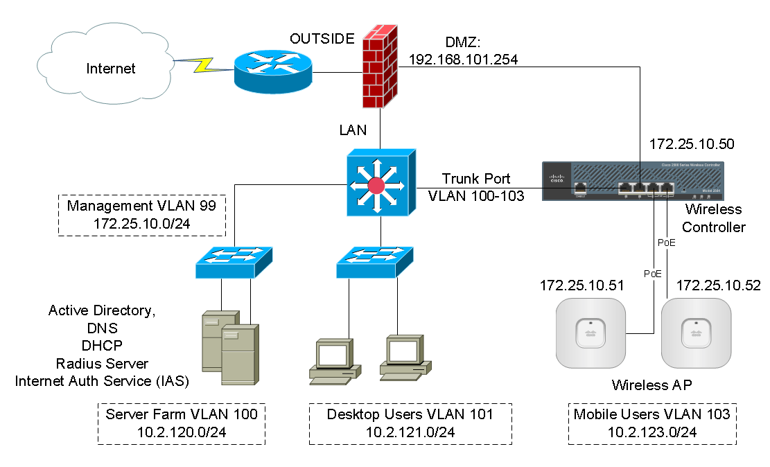
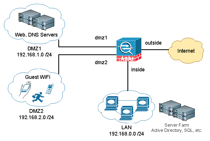
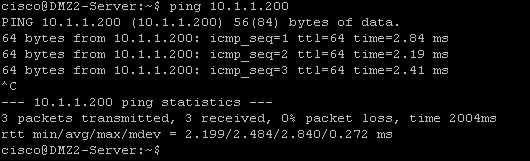
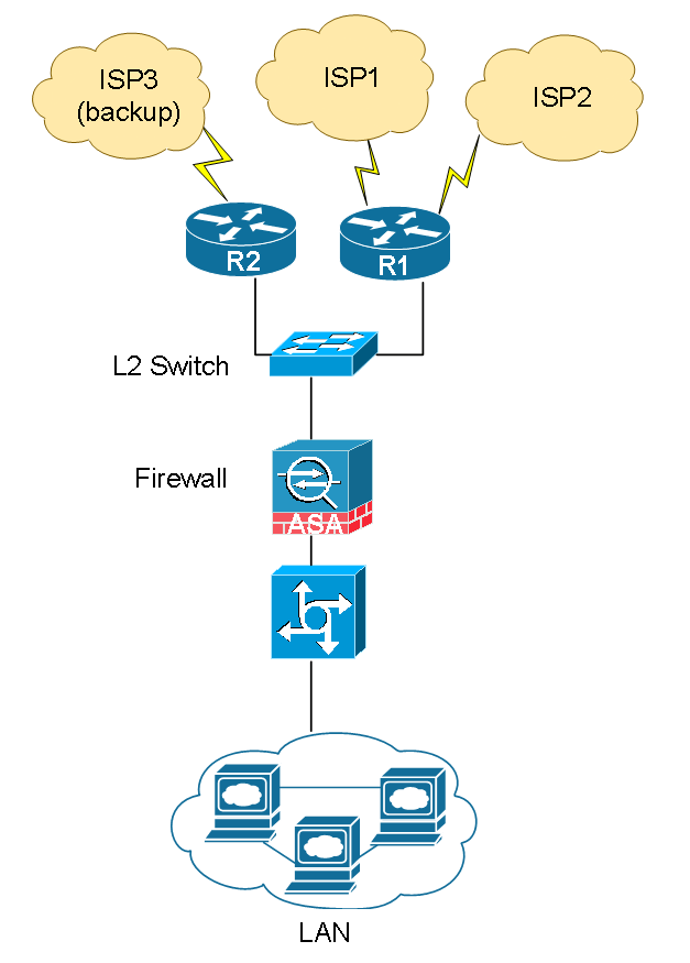
The network diagram below describes common network requirements in a corporate environment.

Cisco_ASA_DMZ (1)

A Cisco ASA is deployed as an Internet gateway, providing outbound Internet access to all internal hosts.

There are four security levels configured on the ASA, LAN, DMZ1, DMZ2 and outside. Their security level from high to low is as following: LAN > DMZ1 > DMZ2 > outside.

  • LAN is considered the most secured network. It not only hosts internal user workstations as well as mission critical production servers. LAN users can reach other networks. However, no inbound access is allowed from any other networks unless explicitly allowed.
  • DMZ1 hosts public facing web servers. Any one on the Internet can reach the servers on TCP port 80. DMZ1 also hosts DNS servers for guest Wi-Fi in DMZ2.
  • DMZ2 is designed as untrusted guest network. Its sole purpose is providing Internet access for visitors. For Internet content filtering, they are required to use the in-house DNS servers in DMZ1.

The design idea here is that we don’t allow any possibilities of compromising the LAN. All “inbound” access to the LAN is denied unless the connection is initiated from the inside hosts. Servers in DMZ1 have two purposes, serving Internet web traffic and DNS resolution queries from DMZ2, the guest Wi-Fi network. We do have DNS servers on the LAN for internal users and servers. But we do not want to open any firewall holes to our most secured network. The worst case assumption is that, in case DMZ2 is compromised since it is the lease controlled network, it can potentially impact DMZ1 because we do have a firewall rules open for DNS access from DMZ2 to DMZ1. Supposed both DMZ1 and DMZ2 are compromised, and the hacker has no way making his way into the LAN subnet because no firewall rules allow any access into the LAN whatsoever.

Security levels on Cisco ASA Firewall

Before jumping into the configuration, I’d like to briefly touch on how Cisco ASAs work in a multi-level security design. The concept is not Cisco specific. It applies to any other business grade firewalls.

By default, traffic passing from a lower to higher security level is denied. This can be overridden by an ACL applied to that lower security interface. Also the ASA, by default, will allow traffic from higher to lower security interfaces. This behavior can also be overridden with an ACL. The security levels are defined by numeric numbers between 0 and 100. 0 is often placed on the untrusted network such as Internet. And 100 is the most secured network. In our example we assign security levels as following: LAN = 100, DMZ1 = 50, DMZ2 = 20 and outside = 0.
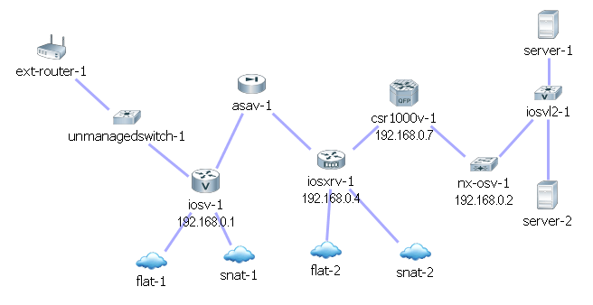
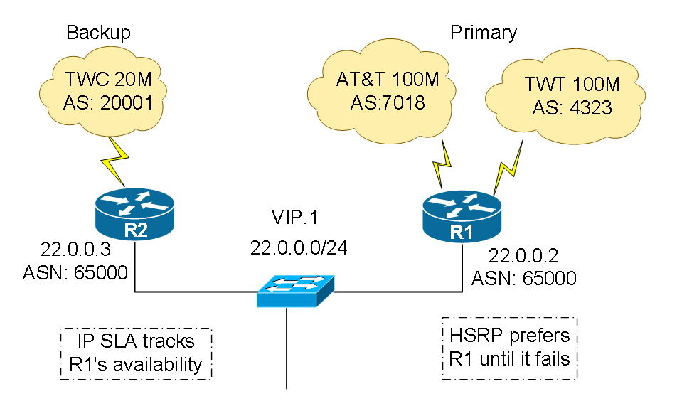
Lab topology setup

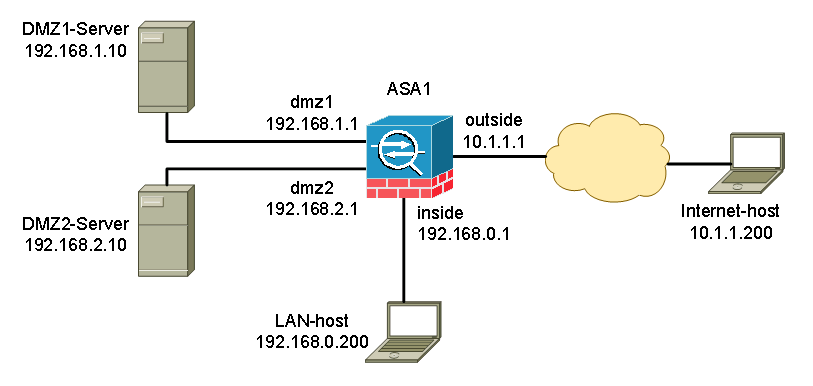
In our lab, we used one host in each network to represent the characteristics of that subnet. A host is placed on the internet side for testing.

Cisco_ASA_DMZ (2)

We’ll first cover the configuration example for ASA code version newer than 8.3, as well as 9.x.

Step 1: Assign security level to each ASA interface

We’ll configure four interfaces on the ASA. Their security levels are: inside (100), dmz1(50), dmz2(20) and outside (0).


interface GigabitEthernet0/0
description to WAN
nameif outside
security-level 0
ip address 10.1.1.1 255.255.255.0
!
interface GigabitEthernet0/1
description to LAN
nameif inside
security-level 100
ip address 192.168.0.1 255.255.255.0
!
interface GigabitEthernet0/2
description to DMZ1
nameif dmz1
security-level 50
ip address 192.168.1.1 255.255.255.0
!
interface GigabitEthernet0/3
description to DMZ2
nameif dmz2
security-level 20
ip address 192.168.2.1 255.255.255.0

Step 2: Configure ASA as an Internet gateway, enable Internet access

There are two main tasks to enable internal hosts to go out to the Internet, configuring Network Address Translation (NAT) and route all traffic to the ISP. You do not need an ACL because all outbound traffic is traversing from higher security level (inside, dmz1 and dmz2) to lower security level (outside).

nat (inside,outside) after-auto source dynamic any interface
nat (dmz1,outside) after-auto source dynamic any interface
nat (dmz2,outside) after-auto source dynamic any interface

The configuration above states that any traffic coming from inside, dmz1 and dmz3 network, translate the source IP to the outside interface’s IP for outbound Internet traffic. The “after-auto” keyword simply set this NAT the least preferred rule to be evaluated after Manual NAT and Auto NAT are evaluated. The reason we want to give it the least preference is to avoid possible conflict with other NAT rules. Let’s talk about the major changes in NAT post-8.3 code briefly.

NAT on the ASA since version 8.3 and later is broken into two types knows as Auto NAT (Object NAT) and Manual NAT (Twice NAT). The first of the two, Object NAT, is configured within the definition of a network object.

The main advantage of Auto NAT is that the ASA automatically orders the rules for processing as to avoid conflicts. This is the easiest form of NAT, but with that ease comes with a limitation in configuration granularity. For example, you cannot make translation decision based on the destination in the packet as you could with the second type of NAT, Manual NAT. Manual NAT is more robust in its granularity, but it requires that the lines be configured in the correct order in order to achieve the correct behavior.

The other change in NAT is that you either define a NAT or you don’t. Traffic that does not match any NAT rules will traverse the firewall without any translation (like NAT exemption but without explicitly configuring it, more like an implicit NAT exemption). The static and global keywords are deprecated. Now it is all about “NAT”.

Next is configuring a default gateway and route all traffic to the upstream ISP. 10.1.1.2 is the gateway the ISP provided.

route outside 0.0.0.0 0.0.0.0 10.1.1.2

At this point, you should be able to ping the host 10.1.1.200 on the Internet from any internet subnets.

Cisco_ASA_DMZ (3) Cisco_ASA_DMZ (4) Cisco_ASA_DMZ (5)

Step 3: Configure static NAT to web servers, grant Internet inbound access to web servers

First we define two objects for the web server, one for its internal IP and one for its public facing IP.

object network WWW-EXT
host 10.1.1.10
!
object network WWW-INT
host 192.168.1.10

We have two ways of configuring NAT, Auto NAT (Object NAT) and Manual NAT (Twice NAT). For Auto-NAT, insert this configuration under WWW-INT object.

nat (dmz1,outside) static WWW-EXT service tcp www www

For Manual NAT, define the web service object and configure manual NAT in global configuration mode. In our example, we’ll demonstrate Manual NAT. You can only have one set of configuration at a time.

object service WEB-SERVICE
service tcp source eq www
!
nat (dmz1,outside) source static WWW-INT WWW-EXT service WEB-SERVICE WEB-SERVICE

When a host matching the ip address 192.168.1.10 on the dmz1 segment establishes a connection sourced from TCP port 80 (WWW) and that connection goes out the outside interface, we want to translate that to be TCP port 80 (WWW) on the outside interface and translate that IP address to be 10.1.1.10.

That seems a little odd… “sourced from TCP port 80 (www)”, but web traffic is destined to port 80. It is important to understand that these NAT rules are bi-directional in nature. As a result you can re-phrase this sentence by flipping the wording around. The result makes a lot more sense:

When hosts on the outside establish a connection to 10.1.1.10 on destination TCP port 80 (www), we will translate the destination IP address to 192.168.1.10 and the destination port will be TCP port 80 (www) and send it out the dmz1.

Because traffic from the outside to the dmz1 network is denied by the ASA by default, users on the Internet cannot reach the web server despite the NAT configuration. We will need to configure ACLs and allow Internet inbound traffic to access the web server.

access-list OUTSIDE extended permit tcp any object WWW-INT eq www
!
access-group OUTSIDE in interface outside

The ACL states, permit traffic from anywhere to the web server (WWW-INT: 192.168.1.10) on port 80.

In earlier versions of ASA code (8.2 and earlier), the ASA compared an incoming connection or packet against the ACL on an interface without un-translating the packet first. In other words, the ACL had to permit the packet as if you were to capture that packet on the interface. In 8.3 and later code, the ASA un-translates that packet before checking the interface ACLs. This means that for 8.3 and later code, traffic to the host’s real IP is permitted and not the host’s translated IP. Note we used WWW-INT in this example.

Step 4: Inter-security segment access control

Let’s recap the default behavior on a Cisco ASA.

  • Traffic initiated from a lower security interface is denied when going to a higher security interface
  • Traffic initiated from a higher security interface is allowed when going to a lower security interface

Specifically in our example,

  • Traffic initiated from “inside” is allowed to go to any other interface segments – “dmz1”, “dmz2” and “outside”.
  • Traffic initiated from “dmz1” is allowed to go to “dmz2” and “outside”. It is denied when going to “inside”.
  • Traffic initiated from “dmz2” is allowed only when going to “outside”. All other segment access is denied.

The default rules can be overwritten by ACLs. In our example, we need the guests in dmz2 to be able to use the DNS servers in dmz1. We’ll need to configure ACLs to specifically allow the access.

! define network objects
object network INSIDE-NET
subnet 192.168.0.0 255.255.255.0
!
object network DMZ1-NET
subnet 192.168.1.0 255.255.255.0
!
! define DNS server object
object network DNS-SERVER
host 192.168.1.10
!
access-list DMZ2-ACL extended permit udp any object DNS-SERVER eq domain
access-list DMZ2-ACL extended deny ip any object INSIDE-NET
access-list DMZ2-ACL extended deny ip any object DMZ1-NET
access-list DMZ2-ACL extended permit ip any any
!
access-group DMZ2-ACL in interface dmz2

The ACLs allow traffic initiated from dmz2 to access the DNS server on UDP port 53. Remember there is an implicit “deny ip any any” at the end of the ACL. If we stopped here dmz2’s Internet access will be broken. We added three more lines to deny access to dmz1 and inside networks while allowing the reset of traffic to go to the Internet.

What about ACLs on dmz1 and inside interfaces? We do not need any ACLs on those interfaces because the default security behavior meets our requirements.

Step 5: Verification and troubleshooting

In this session I will demonstrate a few verification and troubleshooting techniques to quickly validate the configuration and identify the problem if any.

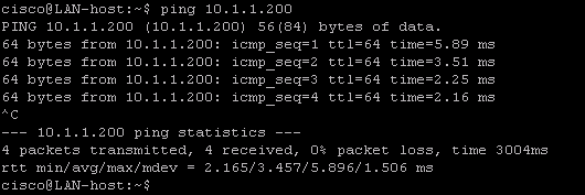
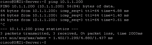
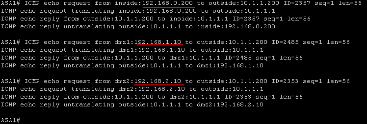
The first technique is using ICMP ping to verify network connectivity. Obviously ping is working does not conclude everything else is also working. However it is a simple tool to confirm that packet from point A can reach point B. In our example we wanted to verify that hosts in each subnet of inside, dmz1 and dmz2 have Internet access. We tried pinging the Internet host at 10.1.1.200 from each internal network.

On the ASA, we enabled ICMP debug mode and made the terminal as the debug message output monitor. By default, the debug messages are sent to the log buffer instead of the screen. You need to view the logs by doing “show logging”. In our case, we wanted to see the logs immediately as they popping up on the screen.

ASA1# debug icmp trace
ASA1# terminal monitor

Ping was initiated from inside host 192.168.0.200, dmz1 host 192.168.1.10 and dmz2 host 192.168.2.10. Responses are being received.

Cisco_ASA_DMZ (6)

Study the debug message and you’ll see exactly how ICMP packets flow through the network.

  1. ICMP echo request from inside:192.168.0.200 to outside:10.1.1.200 (The ASA sees an incoming ping packet from inside interface host 192.168.0.200 and trying to reach host 10.1.1.200 on the outside interface)
  2. ICMP echo request translating inside:192.168.0.200 to outside:10.1.1.1 (The ASA detected a NAT rule would match, and used it to translate the source IP from 192.168.0.200 to 10.1.1.1)
  3. ICMP echo reply from outside:10.1.1.200 to inside:10.1.1.1 (The host 10.1.1.200 on the Internet replied to the ping request and send the return traffic to 10.1.1.1)
  4. ICMP echo reply untranslating outside:10.1.1.1 to inside:192.168.0.200 (The ASA sees the ping return traffic and it matches an established traffic session when the outbound ping traffic was generated. The ASA knows exactly who requested it and who is desperately waiting for it. The ASA un-translate the IP from 10.1.1.1 to 192.168.0.200 and send it to 192.168.0.200).

After testing, do remember to deactivate the debug mode because it is system resource consuming.

ASA1# no debug all

The second technique is using Packet Tracer to simulate packets going through the ASA and see how the ASA treats the packet step-by-step. It is an excellent tool when you do not have access to either side of the servers to generate real traffic. Or before going live, you wanted to make sure the configuration will do what’s intended.

We’ll do two packet tracer tests to validate these critical services:

The ASA will allow inbound web traffic to the web server in DMZ1.

The ASA will allow users in DMZ2 to access the DNS server in DMZ1.

We first simulate web browsing traffic initiated from a host on the internet with IP 10.1.1.200, trying to reach the web server on port 80. The following command sates:

“Generate a fake packet and push it through to the ASA’s outside interface in the inbound direction. The packet comes with source IP 10.1.1.200 using a random high port number 1234 and destination IP 10.1.1.10 to the web server on port 80.”

ASA1# packet-tracer input outside tcp 10.1.1.200 1234 10.1.1.10 http detailed
Phase: 1
Type: ACCESS-LIST
Subtype:
Result: ALLOW
Config:
Implicit Rule
Additional Information:
 Forward Flow based lookup yields rule:
 in  id=0x7fffd1991830, priority=1, domain=permit, deny=false
        hits=43, user_data=0x0, cs_id=0x0, l3_type=0x8
        src mac=0000.0000.0000, mask=0000.0000.0000
        dst mac=0000.0000.0000, mask=0100.0000.0000
        input_ifc=outside, output_ifc=any

Phase: 2
Type: UN-NAT
Subtype: static
Result: ALLOW
Config:
nat (dmz1,outside) source static WWW-INT WWW-EXT service WEB-SERVICE WEB-SERVICE
Additional Information:
NAT divert to egress interface dmz1
Untranslate 10.1.1.10/80 to 192.168.1.200/80

Phase: 3
Type: ACCESS-LIST
Subtype: log
Result: ALLOW
Config:
access-group OUTSIDE in interface outside
access-list OUTSIDE extended permit tcp any object WWW-INT eq www
Additional Information:
 Forward Flow based lookup yields rule:
 in  id=0x7fffd12e7660, priority=13, domain=permit, deny=false
        hits=1, user_data=0x7fffd8eb9d00, cs_id=0x0, use_real_addr, flags=0x0, protocol=6
        src ip/id=0.0.0.0, mask=0.0.0.0, port=0, tag=any
        dst ip/id=192.168.1.200, mask=255.255.255.255, port=80, tag=any, dscp=0x0
        input_ifc=outside, output_ifc=any

Phase: 4
Type: NAT
Subtype:
Result: ALLOW
Config:
nat (dmz1,outside) source static WWW-INT WWW-EXT service WEB-SERVICE WEB-SERVICE
Additional Information:
Static translate 10.1.1.200/1234 to 10.1.1.200/1234
 Forward Flow based lookup yields rule:
 in  id=0x7fffd1cc1b50, priority=6, domain=nat, deny=false
        hits=1, user_data=0x7fffd12e6270, cs_id=0x0, flags=0x0, protocol=6
        src ip/id=0.0.0.0, mask=0.0.0.0, port=0, tag=any
        dst ip/id=10.1.1.10, mask=255.255.255.255, port=80, tag=any, dscp=0x0
        input_ifc=outside, output_ifc=dmz1
...
output omitted for brevity
...
Result:
input-interface: outside
input-status: up
input-line-status: up
output-interface: dmz1
output-status: up
output-line-status: up
Action: allow

Looking through the packet tracer results, we learned the following:

  • Phase 1 is Layer 2 MAC level ACL, we do not have any MAC level restriction configured and all traffic is allowed by default.
  • At Phase 2, packet is being un-NAT’d before sending to the outside interface ACL. That’s why we needed to use the real-IP or the internal IP WWW-INT when configuring the ACL. It is a major change since ASA code 8.3. Prior to code 8.3, ACL was checked first before un-NAT’ing.
  • Phase 3 shows the outside ACL is being verified and the traffic is allowed.
  • The reset of the phases put the packet through various of policy checks such as QoS, policy-maps and etc. We don’t have any of those configured so there was no effect to the packet.
  • In the end, a nice summary is displayed. The input interface is outside, the output interface is dmz1 and the traffic is sent through successfully.

Similarly, we can do the pack tracer testing between dmz2 and dmz1, to verify the host in dmz2 has access to dmz1’s DNS server.

ASA1# packet-tracer input dmz2 udp 192.168.2.10 1234 192.168.1.10 domain detailed
Phase: 1
Type: ACCESS-LIST
Subtype:
Result: ALLOW
Config:
Implicit Rule
Additional Information:
 Forward Flow based lookup yields rule:
 in  id=0x7fffd1a76710, priority=1, domain=permit, deny=false
        hits=12, user_data=0x0, cs_id=0x0, l3_type=0x8
        src mac=0000.0000.0000, mask=0000.0000.0000
        dst mac=0000.0000.0000, mask=0100.0000.0000
        input_ifc=dmz2, output_ifc=any

Phase: 2
Type: ROUTE-LOOKUP
Subtype: Resolve Egress Interface
Result: ALLOW
Config:
Additional Information:
found next-hop 192.168.1.10 using egress ifc  dmz1

Phase: 3
Type: ACCESS-LIST
Subtype: log
Result: ALLOW
Config:
access-group DMZ2-ACL in interface dmz2
access-list DMZ2-ACL extended permit udp any object DNS-SERVER eq domain
Additional Information:
 Forward Flow based lookup yields rule:
 in  id=0x7fffd1cdad10, priority=13, domain=permit, deny=false
        hits=0, user_data=0x7fffd8eb9b80, cs_id=0x0, use_real_addr, flags=0x0, protocol=17
        src ip/id=0.0.0.0, mask=0.0.0.0, port=0, tag=any
        dst ip/id=192.168.1.10, mask=255.255.255.255, port=53, tag=any, dscp=0x0
        input_ifc=dmz2, output_ifc=any
...
output omitted for brevity
...
Result:
input-interface: dmz2
input-status: up
input-line-status: up
output-interface: dmz1
output-status: up
output-line-status: up
Action: allow
  • Since there is no NAT involved, Phase 2 went straight to route lookup. The output interface dmz1 was identified.
  • Phase 3 checks the ACL, and it granted traffic to go through.
  • The reset of the phases stayed the same. In the end, the packet was sent through dmz1 interface successfully.

Both packet tracer results confirmed our configuration is correct. Let try packet tracer testing on something that is not supposed to work. We wanted to see the ASA actually blocks the traffic.

The web server is not configured to serve FTP traffic. We’ll send a FTP request to the webs server and see what happens.

ASA1# packet-tracer input outside tcp 10.1.1.200 1234 10.1.1.10 ftp detailed
Phase: 1
Type: ROUTE-LOOKUP
Subtype: Resolve Egress Interface
Result: ALLOW
Config:
Additional Information:
found next-hop 10.1.1.10 using egress ifc  outside

Result:
input-interface: outside
input-status: up
input-line-status: up
output-interface: outside
output-status: up
output-line-status: up
Action: drop
Drop-reason: (nat-no-xlate-to-pat-pool) Connection to PAT address without pre-existing xlate

The ASA dropped the packet because there is no NAT rules configured to transfer FTP traffic to anything. It didn’t even get to the ACL check point.

Cisco ASA pre-8.3 code configuration

Step 1: Assign security level to each ASA interface (same)

Step 2: Configure ASA as an Internet gateway, enable Internet access

We configure a “global NAT” to use the outside interface IP for Internet surfing. The number “10” is the NAT group ID that will draw from the global NAT. We then define NAT group ID 10 for each internal subnets to use the global NAT.

global (outside) 10 67.52.159.6
nat (inside) 10 192.168.0.0 255.255.255.0
nat (dmz1) 10 192.168.1.0 255.255.255.0
nat (dmz2) 10 192.168.2.0 255.255.255.0

That’s all you needed for outbound Internet.

The default route to the Internet gateway is configured the same.

route outside 0.0.0.0 0.0.0.0 10.1.1.2

Step 3: Configure static NAT to web servers, grant Internet inbound access to web servers

Configure a one-to-one static NAT for the web server. The ACL permits anyone on the Internet to access the web server on port 80. The difference in configuration is that we used publically NAT’d IP instead of the web server’s internal IP in the ACL.

static (dmz1,outside) 10.1.1.10 192.168.1.10 netmask 255.255.255.255
access-list OUTSIDE extended permit tcp any host 10.1.1.10 eq www
access-group OUTSIDE in interface outside

Step 4: Inter-security segment access control

First we configure the ACLs to allow DNS access from dmz2 to dmz1.

access-list DMZ2-ACL extended permit udp any host 192.168.1.10 eq domain
access-list DMZ2-ACL extended deny ip any 192.168.0.0 255.255.255.0
access-list DMZ2-ACL extended deny ip any 192.168.1.0 255.255.255.0
access-list DMZ2-ACL extended permit ip any any
!
access-group DMZ2-ACL in interface dmz2

By default, ASA code prior to 8.3 will try to NAT any traffic going through an interface. We do not want the ASA to perform Network Address Translations among internal interfaces unless the traffic is heading to the outside interface. The configuration below basically states: traffic going from “inside” to “dmz1” or “dmz2” do not NAT (or NAT to the same IP they came with). Same logic applies the traffic going from dmz2 to dmz1.

static (inside,dmz1) 192.168.0.0 192.168.0.0 netmask 255.255.0.0
static (inside,dmz2) 192.168.0.0 192.168.0.0 netmask 255.255.0.0
static (dmz2,dmz1) 192.168.0.0 192.168.0.0 netmask 255.255.0.0

In the packet tracer tests, you may observe that packets are checked by the ACLs before being NAT’d.

That’s all you need to configure on an ASA running pre-8.3 code.

I’d love to hear from you!
If you have any questions regarding the content, feedback or suggestions for future topics, please leave a comment below.

The post Cisco ASA DMZ Configuration Example appeared first on Speak Network Solutions, LLC.


Working With VIRL Topology File Export and Import

$
0
0

One of the advantages of working with Cisco VIRL network simulation is that all the information regarding a simulation including network topology, router configurations and node interconnectivities are stored in a single XML file. The file has an extension of .virl that VM Maestro can open. In this session, we’ll break down the XML file and try to understand its anatomy while working with VIRL topology file export and import. We’ll also explain how to use a pre-configured topology in a different lab environment.

In order to cover all the subtypes and study their specific characteristics in the XML file, I created a network comprised of one of each subtype devices come with VIRL server installation. They include IOSv, IOSvL2, ASAv, CSR1000v, IOS XRv, NX-OSv and Linux servers.

Here is how the topology looks like:

VIRL Topology File Export and Import (1)

Locating the topology file

In a standard installation, VM Maestro stores all the topology files at C:\Users\user-name\vmmaestro\workspace\My Topologies\.

The .virl file is written in clear text XML format. You can open it in any text editor such as Notepad. Extensible Markup Language (XML) is a markup language that defines a set of rules in hierachilcal fashion, for configuraitons in a format which is both human-readable and machine-readable. The design goals of XML emphasize simplicity, generality and usability across the Internet.

High level .virl file structure

topology
node 1
- extensions
   - entry1 node configuration
   - entry2 key type definitions
- interface 1
- interface 2
- interface 3
...
node 2
node 3
...
Connection 1
Connection 2
Connection 3
...
end of topology

Breaking down each session, it is not hard to understand meaning of each session by looking into the content. Node name, type and subtype are defined in the line below, as well as the router’s loopback IP and the coordinate on the canvas map.

<node name="iosv-1" type="SIMPLE" subtype="IOSv" location="265,225" ipv4="192.168.0.1">

The next session is called “extensions”, where router’s configuration and some other attributes are stored. As you can see the configuration below was generated by AutoNetkit with a time stamp. If you choose to use your own configution, you can insert your own.

<extensions>
<entry key="config" type="string">! IOS Config generated on 2015-07-22 16:12
! by autonetkit_0.15.3
hostname iosv-1
boot-start-marker
boot-end-marker
!
no aaa new-model
!
ip cef
ipv6 unicast-routing
ipv6 cef
!
service timestamps debug datetime msec
service timestamps log datetime msec
no service password-encryption
no service config
enable password cisco
ip classless
ip subnet-zero
no ip domain lookup
line vty 0 4
transport input ssh telnet
exec-timeout 720 0
password cisco
login
line con 0
password cisco
!
no cdp run
!
interface Loopback0
description Loopback
ip address 192.168.0.1 255.255.255.255
!
interface GigabitEthernet0/0
description OOB Management
! Configured on launch
no ip address
duplex auto
speed auto
no shutdown
! omitted for brevity

</entry>
<entry key="AutoNetkit.mgmt_ip" type="string"></entry>
</extensions>

After the configuration is defined, VIRL needs to know how many interfaces the router has and what IP address you want to assign to each interface. You must start from Interfac ID 0 and increment sequentially. In this example, interface Gig0/1 has IP 10.0.0.2 with network prefix length of 16, which translates to subnet mask 255.255.0.0.

<interface id="0" name="GigabitEthernet0/1" ipv4="10.0.0.2" netPrefixLenV4="16"/>
<interface id="1" name="GigabitEthernet0/2" ipv4="10.1.0.1" netPrefixLenV4="30"/>
<interface id="2" name="GigabitEthernet0/3"/>
<interface id="3" name="GigabitEthernet0/4"/>

Then you define the next node and so on. At the end of the configuration, we need to let VIRL know how these nodes are inter-connected to each other. In a simulation, each node is assigned with a node ID, so does each interface. In the example below, “note [6]’s interface[1] connects to note[13]’s interface 1”. That’s it. VIRL doesn’t care if it was a FastEthernet or Gig Ethernet port. It only goes by interface IDs.

<connection dst="/virl:topology/virl:node[6]/virl:interface[1]" src="/virl:topology/virl:node[13]/virl:interface[1]"/>
<connection dst="/virl:topology/virl:node[6]/virl:interface[6]" src="/virl:topology/virl:node[1]/virl:interface[1]"/>
<connection dst="/virl:topology/virl:node[7]/virl:interface[1]" src="/virl:topology/virl:node[1]/virl:interface[2]"/>
<connection dst="/virl:topology/virl:node[2]/virl:interface[1]" src="/virl:topology/virl:node[7]/virl:interface[2]"/>
<connection dst="/virl:topology/virl:node[3]/virl:interface[1]" src="/virl:topology/virl:node[2]/virl:interface[2]"/>
<connection dst="/virl:topology/virl:node[4]/virl:interface[1]" src="/virl:topology/virl:node[3]/virl:interface[2]"/>
<connection dst="/virl:topology/virl:node[8]/virl:interface[1]" src="/virl:topology/virl:node[4]/virl:interface[2]"/>
<connection dst="/virl:topology/virl:node[5]/virl:interface[1]" src="/virl:topology/virl:node[8]/virl:interface[2]"/>
<connection dst="/virl:topology/virl:node[14]/virl:interface[1]" src="/virl:topology/virl:node[8]/virl:interface[3]"/>
<connection dst="/virl:topology/virl:node[1]/virl:interface[3]" src="/virl:topology/virl:node[9]/virl:interface[1]"/>
<connection dst="/virl:topology/virl:node[2]/virl:interface[4]" src="/virl:topology/virl:node[12]/virl:interface[1]"/>
<connection dst="/virl:topology/virl:node[1]/virl:interface[4]" src="/virl:topology/virl:node[11]/virl:interface[1]"/>
<connection dst="/virl:topology/virl:node[2]/virl:interface[3]" src="/virl:topology/virl:node[10]/virl:interface[1]"/>

That’s the overall structure of a .virl topology file. Before we move on, I’d like to show you the how those “special nodes” are defined in the .virl file.

A FLAT could is defined as ASSET and has a single interface called “link0” connected to a router. The SNAT cloud is configured the same way.

<node name="flat-1" type="ASSET" subtype="FLAT" location="206,317">
<interface id="0" name="link0"/>
</node>
<node name="flat-2" type="ASSET" subtype="FLAT" location="399,305">
<interface id="0" name="link0"/>
</node>
<node name="snat-1" type="ASSET" subtype="SNAT" location="300,310">
<interface id="0" name="link0"/>
</node>
<node name="snat-2" type="ASSET" subtype="SNAT" location="495,307">
<interface id="0" name="link0"/>
</node>

Similarly, an external router is defined as ASSET and it does not come with any configuration but its coordinates on the canvas and the interface ID.

<node name="ext-router-1" type="ASSET" subtype="EXT-ROUTER" location="74,76">
<interface id="0" name="link0"/>
</node>

Here comes to the fun part. A Linux server is confiugred using cloud-init techology. All the critical aspects of a server are specified in the configuration file.

<node name="server-2" type="SIMPLE" subtype="server" location="635,238" vmFlavor="m1.small [2]">
<extensions>
<entry key="config" type="string">#cloud-config
bootcmd:
- ln -s -t /etc/rc.d /etc/rc.local
hostname: server-2
manage_etc_hosts: true
runcmd:
- start ttyS0
- systemctl start getty@ttyS0.service
- systemctl start rc-local
- sed -i '/^\s*PasswordAuthentication\s\+no/d' /etc/ssh/sshd_config
- echo "UseDNS no" &gt;&gt; /etc/ssh/sshd_config
- service ssh restart
- service sshd restart
users:
- default
- gecos: User configured by VIRL Configuration Engine 0.15.8
lock-passwd: false
name: cisco
plain-text-passwd: cisco
shell: /bin/bash
ssh-authorized-keys:
- VIRL-USER-SSH-PUBLIC-KEY
sudo: ALL=(ALL) ALL
write_files:
- path: /etc/init/ttyS0.conf
owner: root:root
content: |
# ttyS0 - getty
# This service maintains a getty on ttyS0 from the point the system is
# started until it is shut down again.
start on stopped rc or RUNLEVEL=[12345]
stop on runlevel [!12345]
respawn
exec /sbin/getty -L 115200 ttyS0 vt102
permissions: '0644'
- path: /etc/systemd/system/dhclient@.service
content: |
[Unit]
Description=Run dhclient on %i interface
After=network.target
[Service]
Type=oneshot
ExecStart=/sbin/dhclient %i -pf /var/run/dhclient.%i.pid -lf /var/lib/dhclient/dhclient.%i.lease
RemainAfterExit=yes
owner: root:root
permissions: '0644'
- path: /etc/rc.local
owner: root:root
permissions: '0755'
content: |-
#!/bin/sh -e
ifconfig eth1 up 10.1.128.3 netmask 255.255.255.248
route add -net 10.1.0.0/16 gw 10.1.128.1 dev eth1
route add -net 192.168.0.0/28 gw 10.1.128.1 dev eth1
exit 0

As you saw you can specify the server size, file system permissions, user accounts, interface IP addresses, routing table and etc. For the most part, we only care about the interface IPs and routing table. That’s all we essentially needed for the servers to function as a user workstation or a utility server to test the network connectivity.

Import and export network topology files

As mentioned in the beginning of the session, VIRL’s topology file contains all the information to launch a simulation. That has made the simulation highly portable, meaning that you can copy the .virl from one environment to another, import the .virl file and you are good to go.

Let’s start with exporting a topology file from VM Maestro. There are two ways to do it. The easiest and most straightforward way is just go to the topology folder and copy the .virl file. The topology folder is typically located at C:\Users\user-name\vmmaestro\workspace\My Topologies\.

You can also go to Maestro’s menu, File – Export. And select “Export Topology file to File System”. And go through the wizard.

VIRL Topology File Export and Import (2)

Importing a .virl file works in the same fashion. You can either copy over the .virl file or go through the import wizard on Maestro menu, File – Import.

After the new .virl topology files are imported, it is important to note that you need to refresh “My Topologies” folder in Projects panel to see the imported file. VM Maestro does not refresh the files automatically.

VIRL Topology File Export and Import (3)

I’d love to hear from you!
If you have any questions regarding the content, feedback or suggestions for future topics, please leave a comment below.

The post Working With VIRL Topology File Export and Import appeared first on Speak Network Solutions, LLC.

Automatic ISP failover over uneven bandwidth circuits

$
0
0

As the internet bandwidth becomes cheaper, organizations have upgraded their primary circuits to higher capacity circuits with lower cost. Some choose to keep their legacy service provider as a backup circuit. BGP is enabled on the Customer Edge (CE) routers to provide redundancy and load balancing. However given the nature of BGP is a path or distance vector routing protocol, it does not take bandwidth and circuit costs into consideration when making routing decisions. The question comes that how can we design a network so that the circuits with higher capacity and cheaper costs are utilized first. We keep the lower bandwidth or/and higher cost circuit as an “active” backup without losing the automatic failover provided by BGP. In this session, we’ll cover automatic ISP failover over uneven bandwidth circuits using HSRP, IP SLA and BGP technology.

First let’s get familiar with the basic network topology.

Automatic ISP failover over uneven bandwidth Internet circuits (1)

Network overview

  • A network is comprised of three ISPs and two WAN routers R1 and R2.
  • Two high capacity Internet circuits from two ISPs are terminated on R1. We use them as primary circuit.
  • A lower capacity, high cost Internet circuit is terminated on R2. We only want to use it when both primary ISPs are down.
  • WAN circuits failover and fail back should happen in automated fashion.

Design Principle

If there was only R1 with two ISPs, the design is rather simple. With the consideration of R2 and its backup ISP, we need to make sure the network is aware of its existence and automatically shifts traffic to R2 when R1 fails.

The first step is to establish basic BGP connectivity on all three WAN routers with their upstream ISPs. Since we are not a service provider providing Internet transit, and we want to conserve router resources, we’ll configure the WAN routers only to receive ISP’s directly connected prefixes and default route. Because the circuits on R1 have much higher bandwidth capacity, we want to use them for all outbound and inbound traffic. Let’s break down the “outbound” and “inbound” into two separate discussions. Here is our network diagram with IP information.

Automatic ISP failover over uneven bandwidth Internet circuits (2)

Outbound traffic

For outbound traffic, as long as the WAN router has a default route pointing to its upstream provider, user traffic can be forwarded to the Internet. In our case, three WAN routers each learn a default route from their upstream provider. R1 is preferred over R2 to act as the Internet gateway for internal users. This is done by configuring Hot Standby Routing Protocol (HSRP). A VIP is configured with R1 acting as the live gateway. R2 keeps track of R1’s availability, and it takes over R1’s role as soon as R1 is detected down.

Inbound traffic:

When BGP announces our prefix (22.0.0.0/24) to the Internet over multiple ISPs, it is known by other ISPs that there are more than one ways to reach us. This is where the distance-vector BGP routing protocol comes to play. When a user on the Internet wants to reach us, the user’s ISP looks at its routing table and figure out the best and shortest path to connect to our WAN routers. There are many BGP attributes to be considered when making routing decisions. For now, you can think of the shortest path to reach us is the best route to be chosen. What if we don’t want ISP3, the TWC backup circuit to be ever chosen unless it is the only option? There are several techniques we can use to “influence” the Internet to less prefer using ISP3 to reach us. Please note the word “influence”. There is no guarantee that the ISP will not be chosen. The techniques includes prepending AS numbers, using BGP community to advise your upstream provider to less prefer the prefix you announced to them and etc. But they all come with some caveats. Prepending AS numbers works in some cases but it never worked well in real world because AS Path is not the only attribute the Internet transit ISPs evaluate when making routing decisions. Using BGP community to advise your upstream ISP can only affect your directly connected ISP and its peering ISPs. Many times it is a manual process when you have to change the community or withdraw the announcement.

Our design concept works as following: R2 does not announce our prefix until R1 is declared down. We use IP SLA to track the availability of R1, and tell BGP to begin announcing the prefix in case R1 becomes unavailable. In this design, we have full control of when the backup ISP3 is being activated.

Configuration

Step 1: Establish eBGP peering with upstream service providers on each WAN router

On R1 we are peering with AT&T (ASN7018) TWT (ASN4323). And on R2 we are peering with TWC (ASN20001).

! R1
router bgp 65000
no synchronization
bgp log-neighbor-changes
network 22.0.0.0 mask 255.255.255.0
neighbor 12.12.12.1 remote-as 7018
neighbor 12. 12.12.1 description ATT
neighbor 12. 12.12.1 soft-reconfiguration inbound
neighbor 12. 12.12.1 prefix-list ATT-7018-OUT-FILTER out
neighbor 12. 12.12.1 route-map ATT-7018-INBOUND in
neighbor 12. 12.12.1 maximum-prefix 600000 95 warning-only
!
neighbor 206.206.206.1 remote-as 4323
neighbor 206.206.206.1 description TWT
neighbor 206.206.206.1 soft-reconfiguration inbound
neighbor 206.206.206.1 prefix-list TWT-4323-OUT-FILTER out
neighbor 206.206.206.1 route-map TWT-4323-INBOUND in
neighbor 206.206.206.1 maximum-prefix 600000 95 warning-only
no auto-summary
no synchronization
end

Notice the prefix-list and route-map configured within the BGP session. The prefix-list restricts what prefixes we may announce to the Internet. We can only announce /24 or larger public IP blocks that assigned by Internet address authorities and registries. In our example, it is the 22.0.0.0/24 block. The route-map ensures what we get from our upstream providers. We want to make sure we don’t get more than what we asked for because excessive amount of routing information can overwhelm the router and impact performance. maximum-prefix warning is also a good practice to let the router send out syslog warning messages when the amount of prefixes received from upstream exceeded the number defined.

! AT&T inbound and outbound prefixes-lists
ip prefix-list ATT-7018-IN-FILTER seq 10 deny 0.0.0.0/8 le 32
ip prefix-list ATT-7018-IN-FILTER seq 20 deny 10.0.0.0/8 le 32
ip prefix-list ATT-7018-IN-FILTER seq 40 deny 127.0.0.0/8 le 32
ip prefix-list ATT-7018-IN-FILTER seq 50 deny 169.254.0.0/16 le 32
ip prefix-list ATT-7018-IN-FILTER seq 60 deny 172.16.0.0/12 le 32
ip prefix-list ATT-7018-IN-FILTER seq 70 deny 192.0.2.0/24 le 32
ip prefix-list ATT-7018-IN-FILTER seq 80 deny 192.168.0.0/16 le 32
ip prefix-list ATT-7018-IN-FILTER seq 90 deny 224.0.0.0/3 le 32
ip prefix-list ATT-7018-IN-FILTER seq 100 deny 0.0.0.0/0 ge 25
ip prefix-list ATT-7018-IN-FILTER seq 110 deny 22.0.0.0/24 le 32
ip prefix-list ATT-7018-IN-FILTER seq 9999 permit 0.0.0.0/0 le 32
!
ip prefix-list ATT-7018-OUT-FILTER seq 10 permit 22.0.0.0/24
ip prefix-list ATT-7018-OUT-FILTER seq 9999 deny 0.0.0.0/0 le 32

! TWT inbound and outbound prefixes-lists
ip prefix-list TWT-4323-IN-FILTER seq 10 deny 0.0.0.0/8 le 32
ip prefix-list TWT-4323-IN-FILTER seq 20 deny 10.0.0.0/8 le 32
ip prefix-list TWT-4323-IN-FILTER seq 40 deny 127.0.0.0/8 le 32
ip prefix-list TWT-4323-IN-FILTER seq 50 deny 169.254.0.0/16 le 32
ip prefix-list TWT-4323-IN-FILTER seq 60 deny 172.16.0.0/12 le 32
ip prefix-list TWT-4323-IN-FILTER seq 70 deny 192.0.2.0/24 le 32
ip prefix-list TWT-4323-IN-FILTER seq 80 deny 192.168.0.0/16 le 32
ip prefix-list TWT-4323-IN-FILTER seq 90 deny 224.0.0.0/3 le 32
ip prefix-list TWT-4323-IN-FILTER seq 100 deny 0.0.0.0/0 ge 25
ip prefix-list TWT-4323-IN-FILTER seq 110 deny 22.0.0.0/24 le 32
ip prefix-list TWT-4323-IN-FILTER seq 9999 permit 0.0.0.0/0 le 32
!
ip prefix-list TWT-4323-OUT-FILTER seq 10 permit 22.0.0.0/24
ip prefix-list TWT-4323-OUT-FILTER seq 9999 deny 0.0.0.0/0 le 32

In the inbound prefix-list, line sequence from 10 through 110 listed all the prefixes that should never appear on the Internet routing table. Those prefixes are either reserved for research purpose, multicast IP space defined by IPv4 RFC, or, private IPs that should never be routed on the Internet. Also, if the router sees our own prefix 22.0.0.0/24 being announced by upstream provider, we do not want to inject the route ether. Once the routing information passed the prefix-list inspection, it may come in. Very often, attacks and hackers on the Internet spoof their source IPs by using one of the IPs in the list above to carry out the attacks. It is the best practice to implement an extra layer of protection when configuring BGP.

The outbound prefix-list is straightforward. It allows only our prefix 22.0.0.0/24 to be announced to the upstream.

When you request your upstream ISP to peer with you, they will ask what types of routes you want to receive from them. Typically there are 4 options: default route only, default route + ISP routes, ISP routes + their customer routes, and finally the entire Internet routing table. As the time of this article is written, there are about 550,000 routes on the Internet routing table. There is no use for you to receive the entire Internet routing table unless you are an ISP providing IP transit, or for research purpose.

Although you can rely on your ISP not to send the entire Internet routing table to you, in case they messed up their configuration, we want to protect our routers. The configuration below filters the routes received from the upstream ISP and only places the ISP native routes originated from itself, and their customers’ routes into our BGP routing table.

ip as-path access-list 1 permit ^7018_[0-9]*$
ip as-path access-list 2 permit ^4323_[0-9]*$
!
route-map ATT-7018-INBOUND permit 10
match as-path 1
route-map TWT-4323-INBOUND permit 10
match as-path 2

R2 has the similar configuration that we will not cover in details.

Step 2: Configure HSRP on R1 and R2’s internal interface. Give R1 the preference of active Internet Gateway for internet users.

R1 and R2’s configuration is shown below. There are two key features in this configuration:

  1. R1 is set with HSRP priority 105 (R2 uses default 100). R1 becomes the active router serving 22.0.0.1
  2. “track 1” is configured to watch whether the default route 0.0.0.0 /0 is still being leant from the upstream ISP. If the default route disappears, most likely it has lost upstream connection for whatever reason, all outbound traffic will stale. When that happens, a router cannot act as active gateway for users. R1 decrements 10 from its priority 105 and becomes 95. R2 has primary 100 and will take over R1’s role immediately.
! R1
interface GigabitEthernet0/1
description LAN
ip address 22.0.0.2 255.255.255.0
standby 1 ip 22.0.0.1
standby 1 priority 105
standby 1 preempt
standby 1 track 1 decrement 10
end
track 1 ip route 0.0.0.0 0.0.0.0 reachability

! R2
interface GigabitEthernet0/1
description LAN
ip address 22.0.0.3 255.255.255.0
standby 1 ip 22.0.0.1
standby 1 preempt
standby 1 track 1
end
track 1 ip route 0.0.0.0 0.0.0.0 reachability

Show commands verify the status of HSRP and track objects.

R1#sho standby brief
P indicates configured to preempt.
|
Interface   Grp Pri P State   Active         Standby     Virtual IP
Gi0/1       1   105 P Active local           22.0.0.3     22.0.0.1

R1#sho track 1
Track 1
IP route 0.0.0.0 0.0.0.0 reachability
Reachability is Up (BGP)
2 changes, last change 23w0d
First-hop interface is FastEthernet0/0/0
Tracked by:
HSRP GigabitEthernet0/1 1

Step 3: R2 withdraws BGP announcement unless R1 fails

Think about the current situation for a moment. If you stopped at Step 2, all outbound traffic goes through R1 for Internet and the inbound traffic may still go through R2. Recall the requirement, we do not want any traffic go through R2 unless R1 fails. Therefore, we need to configure conditional routing that only activates R2 when R1 fails.

At this time, all the magic happens on R2. We first configure an IP SLA monitor, which keeps track of the reachability of R1’s Ggi0/1 22.0.0.2. It pings R1 once every 60 seconds and repeats indefinitely. “track 2” is configured to watch “ip sla monitor 1”, and declare down state after 90 seconds ( track 1 is in use to track 0.0.0.0/0). Reinstate up state after 120 seconds when the monitor is up.

ip sla monitor 1
type echo protocol ipIcmpEcho 22.0.0.2 source-interface GigabitEthernet0/1
ip sla monitor schedule 1 life forever start-time now
!
track 2 rtr 1 reachability
delay down 90 up 120

A static Null route is used to let BGP processor know a Boolean state: true or false. The actual route does not matter. We chose to use a host route with a non-publically routable IP. This configuration states: install the static route into our routing table only when “track 2” is up. Remove this route when “track 2” is down.

ip route 192.0.3.1 255.255.255.255 Null0 track 2

Let’s check what is happening on R2. Assume R1 is up and healthy.

R2#sho ip sla monitor configuration
SA Agent, Infrastructure Engine-II
Entry number: 1
Owner:
Tag:
Type of operation to perform: echo
Target address: 22.0.0.2
Source Interface: GigabitEthernet0/1
Request size (ARR data portion): 28
Operation timeout (milliseconds): 5000
Type Of Service parameters: 0x0
Verify data: No
Operation frequency (seconds): 60
Next Scheduled Start Time: Start Time already passed
Group Scheduled : FALSE
Life (seconds): Forever
Entry Ageout (seconds): never
Recurring (Starting Everyday): FALSE
Status of entry (SNMP RowStatus): Active
Threshold (milliseconds): 5000
Number of statistic hours kept: 2
Number of statistic distribution buckets kept: 1
Statistic distribution interval (milliseconds): 20
Number of history Lives kept: 0
Number of history Buckets kept: 15
History Filter Type: None
Enhanced History:

R2#sho ip sla monitor statistics
Round trip time (RTT)   Index 1
Latest RTT: 94 ms
Latest operation start time: 13:38:27.887 PDT Sat Sep 5 2015
Latest operation return code: OK
Number of successes: 41
Number of failures: 0
Operation time to live: Forever
Keywords: BGP, ISP, failover, load balance, IP SLA, conditional routing
Track 2 is up because monitor 1 is OK. A static Null route has been installed into the routing table.

R2#sho track 2
Track 2
Response Time Reporter 1 reachability
Reachability is Up
3 changes, last change 4d05h
Delay up 120 secs, down 90 secs
Latest operation return code: OK
Latest RTT (millisecs) 1
Tracked by:
STATIC-IP-ROUTING 0

R2#sho ip route static
192.0.3.0/24 is variably subnetted, 2 subnets, 2 masks
S       192.0.3.1/32 is directly connected, Null0

Now, how does it have anything to do with BGP? In BGP configuration, we inject the static Null route into BGP routing table with caution. Because this Null route disappears when a failure condition is met, we can use it to trigger BGP actions. Specifically, there are two conditions:

Condition 1: normal condition when R1 is up and healthy, life is good:

  • “monitor 1” = OK
  • “track 2” = Up
  • Static Null route is present in routing table and is being redistributed into BGP table.
  • BGP sees the Null route. It does NOT announce our prefix 22.0.0.0/24.

Condition 2: failure condition when R1 is down. We want to shift traffic to the backup router R2:

  • “monitor 1” = Timeout
  • “track 2” = DOWN
  • Static Null route is withdrawn from routing table. It is no longer being redistributed into BGP table.
  • BGP does NOT see the Null route. It begins announcing our prefix 22.0.0.0/24 to the world.
router bgp 65000
no synchronization
bgp log-neighbor-changes
network 22.0.0.0 mask 255.255.255.0
redistribute static route-map STATIC->BGP
neighbor 24.24.24.1 remote-as 20001
neighbor 24.24.24.1 soft-reconfiguration inbound
neighbor 24.24.24.1 prefix-list TWC-20001-IN-FILTER in
neighbor 24.24.24.1 prefix-list TWC-20001-OUT-FILTER out
 neighbor 24.24.24.1 advertise-map ADV-MAP non-exist-map EXIST-MAP
neighbor 24.24.24.1 maximum-prefix 600000 95 warning-only
no auto-summary
end

ip prefix-list PREFIX-192 seq 10 permit 192.0.3.1/32
!
route-map ADV-MAP permit 10
match ip address prefix-list TWC-20001-OUT-FILTER
!
route-map EXIST-MAP permit 10
match ip address prefix-list PREFIX-192
!
route-map STATIC->BGP permit 10
match ip address prefix-list PREFIX-192
set community no-advertise

To protect our BGP neighbors, we don’t want the static Null route to be advertised to the BGP neighbors whatsoever. It was created as a temporary tool to interface between IP SLA and BGP conditional routing. Be careful and never redistribute any routes into BGP table unless you have a specific purpose. Even when you do, make sure the route is not leaked to elsewhere.

Step 4: Validation and troubleshooting

Here we want to validate the configuration under two scenarios. The first one is when everything is working, we want to make sure traffic is sent and received by R1. No traffic should go through R2.

On R1, we validated that it is the active router in HSRP cluster and is serving as the default gateway for users.

R1#sho standby brief
Interface   Grp Pri P State     Active         Standby         Virtual IP
Gi0/1         1   105 P Active     local           22.0.0.3           22.0.0.1

R1 currently has two active BGP neighbors (AT&T and TWT) and from received about 30,000 routes from each ISP respectively.

R13#sho ip bgp summary
Neighbor       V         AS MsgRcvd MsgSent   TblVer InQ OutQ Up/Down State/PfxRcd
12.12.12.1     4       7018 28675976 907674 2220611     0   0    1w6d        30083
206.206.206.1 4       4323 31433535 453937 2220611   0   0     23w0d         33958

To see what prefixes R1 has announced to the world, use the commands below.

R1#sho ip bgp neighbors 12.12.12.1 advertised-routes
Network        Next Hop           Metric LocPrf Weight Path
*> 22.0.0.0/24 0.0.0.0                 0                     32768 i
Total number of prefixes 1

R1#sho ip bgp neighbors 206.206.206.1 advertised-routes
Network         Next Hop           Metric LocPrf Weight Path
*> 22.0.0.0/24 0.0.0.0                 0                     32768 i
Total number of prefixes 1

On R2, we want to validate it has BGP neighbor with the upstream provider, received prefixes. It should not advertise any route to its upstream according to the conditional routing logic we configured.

R2#sho ip bgp summary
Neighbor       V   AS MsgRcvd MsgSent   TblVer InQ OutQ Up/Down State/PfxRcd
24.24.24.1   4   20001 13453573 465107 45954950     0   0 23w0d     32478

R2#sho ip bgp neighbors 24.24.24.1 advertised-routes
Total number of prefixes 0

Per R2’s show command output, it has received 32478 prefixes from its upstream provider TWC (ASN 20001). It does not advertise any route to the upstream. By validating BGP neighbor details, the condition is not met for advertise-map, therefore status = withdraw. No route is advertised to R2’s BGP neighbor.

R2#sho ip bgp neighbors 24.124.24.1
BGP neighbor is 24.124.24.1, remote AS 20001, external link
...
For address family: IPv4 Unicast
BGP table version 45956558, neighbor version 45956542/0
Output queue size : 0
Index 1, Offset 0, Mask 0x2
1 update-group member
Inbound soft reconfiguration allowed
Incoming update prefix filter list is TWC-20001-IN-FILTER
Outgoing update prefix filter list is TWC-20001-OUT-FILTER
Condition-map EXIST-MAP, Advertise-map ADV-MAP, status: Withdraw

One final thing we need to check is that from the Internet’s perspective, whether or not our prefix 22.0.0.0/24 is seen by the world. And how it is seen. We can use a tool called BGP Looking Glass.

A looking glass is usually a website that interfaces with routers that are owned and operated by a single ISP or other network operator. Most of the time they are publicly accessible. The looking glass provides a view into a BGP table of a particular router in an ISP’s network. Often, looking glass implementations will also include other utilities, such as the ability to run a traceroute to a destination as if it were run from the ISP’s router itself. Looking glasses are useful because they provide a perspective into an upstream’s BGP table. Here we used Equinix’s public route server. Equinix is an American public company that provides carrier-neutral data centers and Internet exchanges to enable interconnection.

To access the router server, telnet to route-views.eqix.routeviews.org.

route-views.eqix-ash> sho ip bgp 22.0.0.0/24 long
BGP table version is 0, local router ID is 206.206.206.2
Status codes: s suppressed, d damped, h history, * valid, > best, i - internal,
r RIB-failure, S Stale, R Removed
Origin codes: i - IGP, e - EGP, ? - incomplete
Network         Next Hop           Metric LocPrf Weight Path
*> 220.0.0.0/24   206.206.206.37                0 6939 4323 14504 I   <- TWT
*                   206.206.206.25         82             0 6079 4323 14504 i
*                   206. 206.206.36                         0 41095 4323 14504 i
*                   206. 206.206.26                         0 16559 4323 14504 i
*                   206. 206.206.12           0             0 2914 7018 14504 I     <- T&T
*                   206. 206.206.172                       0 11039 4901 11164 4323 14504 i
*                   206. 206.206.24                         0 11666 3356 4323 14504 i
*                   206. 206.206.19           0             0 3257 3356 4323 14504 i
*                   206. 206.206.36                         0 4589 4323 14504 i
*                   206. 206.206.76           0             0 5769 6453 3356 4323 14504 i
*                   206. 206.206.47           0             0 19151 4323 14504 i

As we see from the show command output, our prefix 22.0.0.0/24 was learned via number of ways. All of them were coming from either TWT or AT&T. This particular router has chosen TWT as the best path to reach us. Please note different service provider has different perspective of view on the Internet. Even within the same ISP, different router may choose different path to reach a specific prefix. It is totally up to the routing decision on a particular router.

The second scenario we wanted validate is that when R1 fails, R2 takes over and makes announcement to the world that he is now in charge. In order to test, we introduced a failure condition by shutting downR1. Looking into R2’s neighbor details, we found that the advertise-map condition is met and our prefix is now advertised to R2’s upstream.

R2#sho ip bgp neighbors 24.124.24.1
BGP neighbor is 24.124.24.1, remote AS 20001, external link
...
For address family: IPv4 Unicast
BGP table version 45956558, neighbor version 45956542/0
Output queue size : 0
Index 1, Offset 0, Mask 0x2
1 update-group member
Inbound soft reconfiguration allowed
Incoming update prefix filter list is TWC-20001-IN-FILTER
Outgoing update prefix filter list is TWC-20001-OUT-FILTER
Condition-map EXIST-MAP, Advertise-map ADV-MAP, status: Advertise

From the Internet Looking Glass, we now see only TWC (ASN 20001) is advertising our route to the world.

route-views.eqix-ash> sho ip bgp 22.0.0.0/24 long
BGP table version is 0, local router ID is 206.206.206.2
Status codes: s suppressed, d damped, h history, * valid, > best, i - internal,
r RIB-failure, S Stale, R Removed
Origin codes: i - IGP, e - EGP, ? - incomplete
Network         Next Hop           Metric LocPrf Weight Path
*> 206.206.206.76           0             0 5769 7843 20001 14504 i   ! <- TWC

Conclusion

As we have demonstrated, we did not have to use any of the BGP attributes such as weight, local preference, multi-exit discriminator (MED) and so on to accomplish the goal. BGP is a very complex routing protocol and it also provides greater flexibility. With other technology like IP SLA, object tracking and conditional routing combined, the possibilities are unlimited.

I’d love to hear from you!
If you have any questions regarding the content, feedback or suggestions for future topics, please leave a comment below.

The post Automatic ISP failover over uneven bandwidth circuits appeared first on Speak Network Solutions, LLC.

Cisco VIRL Installation on Bare-metal Standalone Server

$
0
0

In some cases you may prefer installing Cisco VIRL on its dedicated hardware without running on a virtual machine. Most personal users do not have the luxury of access to business grade VMWare infrastructure. Some are studying for CCNA, CCNP and CCIE labs and would like to build a home lab using their existing computers. I’ve also seen businesses prefer putting VIRL on its dedicated server to achieve better performance by eliminating the VM hypervisor overhead, as well as separating it from production environment. In this session, we’ll cover Cisco VIRL installation on bare-metal standalone server.

Updated for new VIRL release 1.0.0 on Nov. 15th 2015.

Hardware Requirements

  • The server must support Intel VT-X/EPT or AMD-V/RVI virtualization extensions.
    You may wonder why the hardware needs to support VT-X virtualization technology even though our Cisco VIRL installation will be on a bare-metal standalone server. VIRL in fact is also a VM host. It utilizes OpenStack technologies and each simulated router inside it is a virtual instance. What this means is that the VIRL server you deployed on your computer or dedicated server will in turn deploy virtual machines within itself. It is called nested virtualization. For this to function properly we need to be able to pass the CPU “flags” from the server to VIRL and VIRL’s virtual machine. In essence, tricking the virtual instances to think that they have direct access to the CPU. You must enable above mentioned virtualization technology in BIOS. (instructions shown later)
  • Minimum of 60GB hard disk space.
  • Minimum 4GB of RAM.
    If you need to simulate more than 10 nodes at same time, 8GB or more is recommended, 16GB or 24GB is preferred.
  • VIRL wants you to have five dedicated Network Interfaces (NICs).
    I found you can get alone with just one, preferably two NICs and configure the rest as “dummy” interfaces. In my opinion, it is not necessary to setup five dedicated NICs since 3-5 are rarely used in most common lab setups I came across.

For demonstration, I used a Dell PowerEdge server for this tutorial. Here are its specs.

  • Dell PowerEdge R310 1U Server
  • Intel Xeon X3440 2.53GHz Quad Core Processor
  • 24GB RAM (6x4GB)
  • PERC i/6 RAID Controller
  • 2x 450GB 15k RPM 3.5″ SAS Hard Drives, configured RAID1 (mirror)

Now let’s get started.

Cisco VIRL Installation on Bare-metal Standalone Server

Step 1: Obtain Cisco VIRL ISO bootable image

You can purchase a copy of VIRL license on VIRL.cisco.com. You’ll need to login with your Cisco.com account and make the purchase. You’ll receive an email with the instruction how to download the image and the license key. The ISO image is about 2.98GB. An MD5 hash sum for each package is provided along with the download link and on the download website.  To avoid deploying corrupted file, make sure to verify that the hash sum of the downloaded image matches the source. The ISO image used for this tutorial was “virl.1.0.0.iso”.

  • On a Mac OS X use the command “md5 filename”
  • On Linux use the command “md5sum filename”
  • On Windows PC, you may download the free MS File Checksum Integrity Verifier tool. Microsoft File Checksum Integrity Verifier.

Burn a DVD using the ISO image downloaded. You now have a VIRL installation DVD ready to go.

Step 2: Prepare the server for installation

Optionally, you want to run firmware update utility to update all the drivers on the server. We used Dell Repository Manager to update BIOS, RAID controller and System board drivers. This step is optional but recommended. If you are building VIRL on a used server or computer, you may want to bring all the firmware up to date to work with the current technologies.

If your server supports RAID, it is a good time to build an array to provide hard disk redundancy. In this example we configured RAID1 across two 450GB hard disks. Data are mirrored across two disks. No data lost in case one hard disk fails. RAID5 is also a very common configuration. You need to at least three hard disks to build RAID5.

Next, “virtualization technology” needs to be enabled in BIOS. In my case it is not enabled by default. Included screenshots where to find it on the Dell PowerEdge R310.

VIRL Installation on Bare-metal Standalone Server (1)

VIRL Installation on Bare-metal Standalone Server (2)

VIRL Installation on Bare-metal Standalone Server (3)

For your reference, here are some additional screenshots from other types of computers and servers. You can find in Cisco VIRL Installation on VMWare ESXi.

Step 3: Install VIRL on the server

You must boot to “live – boot VIRL for changes before install” first.

VIRL needs to make changes to the default actions before actual installation. The installation will fail if you go directly to the second option “install – start the VIRL installer directly”. I have tested it and I ran into a blank screen during boot up and had to power cycle the server.

VIRL Installation on Bare-metal Standalone Server (4)

VIRL Installation on Bare-metal Standalone Server (5)

VIRL Installation on Bare-metal Standalone Server (6)

The default username / password is virl / VIRL. Once logged in, double click on “Install System to HDD” icon on the desktop and go through the wizard.

VIRL Installation on Bare-metal Standalone Server (7)

I had a Windows 2008 R2 running on the server and I am not planning to use it any more. For my installation, I’m going to have VIRL overwrite everything on my HDD and use it as a dedicated VIRL server. Do select “User LVM with the new system installation”.

VIRL Installation on Bare-metal Standalone Server (8)

ciscovirlbaremetalstandalone

Here you are asked to enter information about the VIRL server. Be sure to change and match the following, otherwise services such as OpenStack will fail to install.

  • Your computer’s name: virl
  • Pick a username: virl
  • Choose a password: VIRL (upper case)

The rest of the wizard is straight forward. Select your time zone and language and start installation. VIRL will copy all the necessary files to your HDD.

VIRL Installation on Bare-metal Standalone Server (9)

This process can take several minutes. Once the installation has finished, click on Restart Now to reboot the system. Boot directly to the HDD as opposed to the DVD this time. You now have VIRL installed on your server.

VIRL Installation on Bare-metal Standalone Server (10)

Step 4: Post installation tasks

There are a few issues that need to be addressed before the VIRL server will function.

Issue 1: Replace “eth” interface descriptor with “em”.

The Ubuntu OS has changed its interface naming scheme from “eth” to “em”. The interface naming now is em1, em2, instead of eth0 and eith1. I found this version of VIRL ISO release does not have the adjustment in place. It causes the operating system fail to recognize it NIC configuration. You can see in the logs.

dmsg | grep eth shows that “renamed network interface eth0 to em1” and eth1 to eth2.

We will address the issue by editing “/etc/network/interfaces” file as well as “/etc/virl.ini”. While we are editing these files, we will assign a static IP for management. The management IP can be used to SSH to the VIRL server remotely.

sudo vi /etc/network/interfaces

Replace all “eth0” with “em1” and “eth1” with “em2”. The server does not have more than two NICs. Any other interfaces configured are irrelevant.

Create an alias for the OpenStack service address. Note that you only use “em” interface descriptor from this point.

up ip addr add 172.16.10.250/24 dev em1

Edit “em1” interface configuration, change from DHCP to static, and assign the management IP to em1. In our example, the management IP is 172.30.30.100. Here is how my /etc/network/interfaces file looked like:

auto em1
iface em1 inet static
address 172.30.30.100
netmask 255.255.255.0
post-up ip link set em1 promisc on
dns-nameservers 8.8.8.8 8.8.4.4
gateway 172.30.30.1
up ip addr add 172.16.10.250/24 dev em1

auto em2
iface em2 inet static
address 172.16.1.254/24
netmask 255.255.255.0
post-up ip link set em2 promisc on
 
auto lo:1
iface lo:1 inet loopback
address 127.0.1.1
netmask 255.0.0.0

auto lo
iface lo inet loopback

Next we need to edit /etc/virl.ini file by replacing “eth” with “em”, and adding “dummy” interfaces.

Search for the following lines of configuration and match them with this:

public_port: em1
using_dhcp_on_the_public_port: False
l2_port: em2
l2_port2: dummy0
l3_port: dummy1
dummy_int: True
internalnet_port: dummy2

Save the file and reboot server. “sudo reboot now”.

Once the server has rebooted, we should be able to SSH to the server using its management IP 172.30.30.100. However I encountered the issue below preventing me from logging in remotely.

Issue 2: Could not SSH to the VIRL server. “Connection reset by peer”.

I troubleshot the issue by monitoring the server’s log file while attempting to SSH.

tail -f /var/log/auth.log

Add -v to get a verbose output at the client end.

ssh virl@172.30.30.100 -v

This might give you more details about the cause. In my case the rsa and dsa keys are missing or mismatch on the server, fixed them by recreating rsa and dsa keys on the VIRL server. Go to the VIRL server and open Terminal, and issue the following commands.

ssh-keygen -t rsa1 -f /etc/ssh/ssh_host_rsa_key
ssh-keygen -t dsa -f /etc/ssh/ssh_host_dsa_key

Here is a screenshot how it looked like on my server.

VIRL Installation on Bare-metal Standalone Server (11)

Once the RSA and DSA keys are regenerated, you should be able to log in the server remotely using SSH.

Issue 3: “nova service-list” and “neutron agent-list” will not work.

If you had tried installing VIRL by following Cisco’s official documentation, you may find neither of these verification would work. You must make sure NTP server is working and finish VIRL activation before the verification commands would work. You may skip this step and move on to the next.

Step 5: Preparing for VIRL activation

Confirm KVM acceleration can be used by running this verification command.

virl@ubuntu:~$ sudo kvm-ok
INFO: /dev/kvm exists
KVM acceleration can be used

For VIRL activation to work, NTP serivce must be running and time has to be synced.

Edit /etc/ntp.conf and replace “eth0” with “em1”.

interface listen em1

Restart NTP service.

virl@ubuntu:~$ sudo service ntp restart
* Stopping NTP server ntpd                                   [ OK ]
* Starting NTP server ntpd                                   [ OK ]

Give it a few minutes for NTP service to talk to the time servers and synch with them. Run “sudo ntpq –p” to confirm that the NTP server is talking to the time servers and the local time has been synched with one of them with asterisk (‘*’).  Display the current time using command “sudo date”.

VIRL Installation on Bare-metal Standalone Server (12)

Step 6: Activate VIRL

From this point, you can reference Cisco VIRL Installation on VMWare ESXi, Step 7: License Activation. The process is the same.

In this session, we’ve covered Cisco VIRL Installation on Bare-metal Standalone Server. If you have any questions regarding the content, feedback or suggestions for future topics, please leave a comment below. I’d love to hear from you!

The post Cisco VIRL Installation on Bare-metal Standalone Server appeared first on Speak Network Solutions, LLC.

Enable Intel-VT and AMD-V Support Hardware Accelerated KVM Virtualization Extensions

$
0
0

As virtualization technologies become mature, with the support of super-fast, extremely robust server hardware, everything seems can be virtualized. In a modern datacenter, you’ll see the entire IT infrastructure being virtualized, including servers, workstations, network devices, storage, PBX and so on. Have you heard of “nested virtualization”? It simply means that you are running virtual machines inside virtual machines by utilizing technologies like OpenStack. Make sure you enable Intel-VT and AMD-V Support Hardware Accelerated KVM Virtualization Extensions to gain full advantage of the virtualization technologies. Here is why-

One of the challenges that virtualization faced was that when running a guest OS under virtual environment, the guest OS does not have direct access to the server hardware such as CPU and RAM without going through the hosting system like VMWare ESXi. Until the Intel VT and AMD-V virtualization technology were developed, modifications must be done to the guest OS to emulate its access to CPU. This had significant performance impact to the guest virtual servers.

Hardware accelerated virtualization solved this problem by proving certain instructions or extensions so that the guest OS appears to have direct access to the server hardware. Intel VT and AMD’s AMD-V are instruction set extensions that provide hardware assistance to virtual machine monitors. They enable running fully isolated virtual machines at native hardware speeds, with minimum overhead.

Enable Intel-VT and AMD-V Support Hardware Accelerated KVM Virtualization Extensions

enableIntelVTXAMDvirtualization

Hardware Requirements

CUP support

Does my CPU support Virtualization Technology? To verify, you can reference the following websites.

Intel: http://www.intel.com/support/processors/sb/cs-030729.htm

AMD: http://products.amd.com/

A processor with Intel-VT does not guarantee that virtualization works on your system. It requires a computer system with a chipset, BIOS, enabling software and/or operating system, device drivers, and applications designed for this feature.

If the BIOS includes a setting to enable or disable support for Intel VT, make sure it is enabled. For Intel® Desktop Boards, enter the BIOS by pressing the F2 key as the system starts.

BIOS support

Once you confirmed that you have a CPU supports virtualization technology, next to check if your motherboard supports it and it is enabled in BIOS settings. Usually most recent motherboards have virtualization support but cross check this information by reading the motherboard manual.

I’ve attached a few screenshots taken from different servers and PCs for your reference. The setting is typically located in System Services – Processor Settings.

VIRL Installation on Bare-metal Standalone Server (1) VIRL Installation on Bare-metal Standalone Server (2) VIRL Installation on Bare-metal Standalone Server (3)

enable-vt-x-in-bios1 enable-vt-x-in-bios2

Verification

On a Linux based systems, /proc/cpuinfo will tell you if the processor supports virtualization and if it is enabled.

cat /proc/cpuinfo | grep “vmx \| svm”

We are essentially looking for “vmx” and “svm” flags. Here is what all the flags mean.

  • vmx — Intel VT-x, basic virtualization
  • svm — AMD SVM, basic virtualization
  • ept — Extended Page Tables, an Intel feature to make emulation of guest page tables faster.
  • vpid — VPID, an Intel feature to make expensive TLB flushes unnecessary when context switching between guests.
  • npt — AMD Nested Page Tables, similar to EPT.
  • tpr_shadow and flexpriority — Intel feature that reduces calls into the hypervisor when accessing the Task Priority Register, which helps when running certain types of SMP guests.
  • vnmi — Intel Virtual NMI feature which helps with certain sorts of interrupt events in guests.

Verify AMD-V CPU virtualization extensions on a Linux

# grep --color svm /proc/cpuinfo

Verify Intel or AMD 64 bit CPU

grep -w -o lm /proc/cpuinfo | uniq

On a Ubuntu server the following commands can be used to verify VT-X is enabled.

lscpu | egrep 'Arch|On-Line|Vend|Virt'
egrep -wo 'vmx|ept|svm|npt|ssse3' /proc/cpuinfo | sort | uniq

Cisco-Virl-installation11

Confirm KVM acceleration can be used by running this verification command.

$sudo kvm-ok
INFO: /dev/kvm exists
KVM acceleration can be used

If kvm-ok command isn’t there, you need to install the KVM module. There are two different brands of virtualization (from Intel and AMD) which are incompatible. Therefore KVM has separate device drivers for each.

To load KVM on an Intel processor:

modprobe kvm_intel

To load KVM on an AMD processor:

modprobe kvm_amd

To verify the module is loaded, use “dmesg” and “lsmod” as root.

In this session we covered how to enable and verify Intel-VT and AMD-V Support Hardware Accelerated KVM Virtualization Extensions. Intel VT (Virtualization Technology) is the company’s hardware assistance for processors running virtualization platforms. Intel VT includes a series of extensions for hardware virtualization. The Intel VT-x extensions are probably the best recognized extensions, adding migration, priority and memory handling capabilities to a wide range of Intel processors.

The post Enable Intel-VT and AMD-V Support Hardware Accelerated KVM Virtualization Extensions appeared first on Speak Network Solutions, LLC.

Cisco ASA 5506-X FirePOWER Configuration Example Part 1

$
0
0

Since Cisco’s acquisition of SourceFire in 2013, Cisco has incorporated one of the best leading Intrusion Prevention System (IPS/IDS) technologies into its “next-generation” firewall product line. Cisco’s ASA firewalls with Sourcefire’s FirePOWER Services are designed to provide contextual awareness to proactively assess threats, correlate intelligence, and optimize defenses to protect networks. I will walk you through step-by-step Cisco ASA 5506-X FirePOWER Configuration Example. The configuration also applies to the product family, ASA 5508-X, 5516-X and 5585-X.

ASA FirePOWER SourceFire Configuration

Cisco ASA 5506-X FirePOWER Configuration Example

Introduction

Cisco ASA 5506-X with FirePOWER module is the direct upgrade path from legacy Cisco ASA5505. It incorporated the industry leading IPS technologies, provides next-generation Intrusion Prevention (NGIPS), Application Visibility and Control (AVC), Advanced Malware Protection (AMP) and URL Filtering. It is available in desktop model 5506-X, integrated wireless access point model 5506W-X and a ruggedized model 5506H-X for industrial control systems and critical infrastructure environment.

Major Differences Compared to Legacy ASA 5500s

  • The new “X” models are running on multicore 64-bit processors compared with single core 32-bit processors on older ASA models.
  • The “X” models have much higher CPU and Memory capacity, provide much higher traffic throughput compared to the same class. It has also made itself FirePOWER ready.
  • The “X” models are next-generation firewalls. With subscription to additional licenses, you can have either Cloud based Web Security / Essentials or running local FirePOWER in software. (except for ASA 5585-X in hardware) The Cloud based security suite was Cisco’s legacy solution before adopting SourceFire solution. I recommend getting the FirePOWER option instead of the Could based solution, since it may be phased out in the near future.
  • Routed interfaces instead of switched interface on the legacy ASA5505. The Cisco ASA5506-X has 8xGE routed interfaces, 1xGE MGMT, RJ45+USB mini console ports. It provides greater flexibilities of using physical interfaces (as opposed using sub-interfaces) to create multiple security zones using DMZ networks. This change is appreciated by medium to enterprise sized businesses customers. However for SOHO users who used to connect PCs directly to the ASA 5505, you will need to add a layer 2 switch on the LAN.
  • The new ASA 5506W-X provides integrated Wireless Access Point, which is good for SOHO users. The ruggedized model 5506H-X, can be suitable for outdoor applications
  • The new ASA 5506-X has a new interface naming conversion that starts from Gig1/1 instead of Gig0/0. I’m not sure why Cisco made such change, it only added unnecessary translation work for ones migrating from legacy models.

ASA FirePOWER SourceFire Configuration (2)

Traffic Flow

Similar to deploying a standalone IPS solution, the integrated FirePOWER module supports “inline” mode and “passive monitoring” mode. “Inline” mode provides additional benefits than monitoring mode. FirePOWER deployed in “inline” mode provides best case deep inspection analysis before packets are returned to the ASA main plane. It proactively takes action when malicious traffic is detected.

When traffic enters ASA’s ingress interface:

  1. The ASA decrypts the traffic if it was part of an established VPN tunnel.
  2. Packets are checked against firewall policies such as ACL, NAT and Inspection.
  3. Optionally, traffic is sent to the FirePOWER Module for deeper level inspection. You may configure to send all traffic or only high risk traffic to the FirePOWER module to conserve system resources.
  4. Traffic passed FirePOWER inspection is returned to the ASA main engine for next step routing decision.
  5. Traffic is then passed to the ASA’s egress interface to be forwarded to the rest of the network.

ASA FirePOWER SourceFire Configuration (1)

Licensing Options

In order to utilize any of the ASA’s next-generation firewall features, Cisco made customers order subscription based licenses for the FirePOWER module to work. The subscription based licenses can be purchased annually, 3 or 5 years with discount. Here are list of licenses available:

  • Intrusion detection and prevention (IPS license)
  • Application Visibility and Control (AVC)
  • File control and advanced malware protection (AMP)
  • Application, user, and URL control (URL Filtering)
  • IPS license is required for the AVC, AMP and URL Filtering license.

Management Options

Even though the FirePOWER module is integrated in to one ASA platform, it is managed separately from the ASA configuration. You have two options of managing and operating the FirePOWER module- Distributed management model and Centralized management model.

Distributed model using ASDM: For standalone single site deployment.

Suitable for SOHO customers who do not have more than 3 locations and do not want to manage a separate sever infrastructure.

Centralized model using FirePOWER Management Center

The Management Console is a hardware or virtual appliance installed centrally to manage multiple FirePOWER deployments at same time. Suitable for enterprise customers who have more than 5 locations deployed with FirePOWER.

Continue reading:

Cisco ASA 5506-X FirePOWER Configuration Example Part 2

Configure and Manage ASA FirePOWER Module using ASDM Part 3

Configure and Manage ASA FirePOWER Module using Management Center Part 4

The post Cisco ASA 5506-X FirePOWER Configuration Example Part 1 appeared first on Speak Network Solutions, LLC.

Cisco ASA 5506-X FirePOWER Configuration Example Part 2

$
0
0

In this example, we’ll step through Cisco ASA 5506-X FirePOWER configuration example and activate the FirePOWER module in a typical network. We used ASA 5506-X running code 9.5(2) and ASDM version 7.5(2).

Before proceed, please make sure the followings are taken into consideration. If you are configuring a brand new ASA 5506-X, you may skip to Step 1.

  • It is not recommended to configure and run Could Web Security (ScanSafe) at the same time running FirePOWER. Technically it is possible to split traffic to be inspected by one of the method respectively, however it is not recommended.
  • Do not enable ASA’s HTTP inspection features since FirePOWER provides more advance HTTP inspection than ASA.
  • Cisco Mobile User Security (MUS) is not compatible with FirePOWER.

Cisco ASA 5506-X FirePOWER Configuration Example

Step 1: Update ASA software and ASDM code

Download the recent stable release from Cisco.com and transfer the codes to the ASA.

ASA FirePOWER SourceFire Configuration (2)

Set the system to boot to the new image. Configure the ASDM image to be used.

ASA1(config)# boot system disk0:/asa952-lfbff-k8.SPA
ASA1(config)# asdm image disk0:/asdm-752.bin 

Write memory and verify the bootvar is set correctly. Reboot the system to load the new image.

ASA FirePOWER SourceFire Configuration (3)

Step 2: Verifying FirePOWER module status

Using “show module”, you can verify the FirePOWER module is online and healthy.

ASA1# sho module

Mod Card Type                                  Model             Serial No.
---- -------------------------------------------- ------------------ -----------
ASA 5506-X with FirePOWER services, 8GE, AC, ASA5506           JAD19280XXX
sfr FirePOWER Services Software Module          ASA5506           JAD19280XXX
Mod MAC Address Range                 Hw Version   Fw Version   Sw Version
---- --------------------------------- ------------ ------------ ---------------
1 5897.bd27.58d6 to 5897.bd27.58df 1.0         1.1.1       9.5(2)
sfr 5897.bd27.58d5 to 5897.bd27.58d5 N/A         N/A         5.4.1-211
Mod SSM Application Name           Status           SSM Application Version
---- ------------------------------ ---------------- --------------------------
sfr ASA FirePOWER                 Up               5.4.1-211
Mod Status             Data Plane Status     Compatibility
---- ------------------ --------------------- -------------
1 Up Sys             Not Applicable
sfr Up                 Up

Step 3: Physical cabling

On ASA 5506-X through ASA 5555-X platforms, the ASA itself and FirePOWER module share the same physical management interface (ASA 5585-X has dedicated management interface for each). For the shared management interface, you have two options to configure.

Option 1: Dedicate the management interface to FirePOWER, and manage the ASA through its inside or outside interface.

In order to run in this mode, you must not configure a name on the management interface. You need to configure a FirePOWER management IP on the same network as inside interface of the ASA. In our example, we have 192.168.0.1 on the inside interface and 192.168.0.2 on the management interface.

Keep in mind that FirePOWER management interface must have internet access for signature updates and communication to the Management Center. Traffic cannot pass through the ASA’s backbone. Instead, management traffic must enter and exit through the same physical port. Illustrated below is a typical cabling setup where management interface is connected to the same layer 2 switch as the inside network.

ASA FirePOWER SourceFire Configuration (4)

Option 2: Share management interface between ASA and FirePOWER

If you have a layer 3 device such as a layer 3 switch on your network, this method of configuration is recommended. The ASA and the FirePOWER module share the same physical management interface with different IP addresses. The management IP addresses are on a separate network or VLAN, dedicated to management traffic. Internet bound traffic initiated from the management IP is routed through the layer 3 device to the inside interface of the ASA.

ASA FirePOWER SourceFire Configuration (5)

In our example, we assigned 192.168.1.1 for ASA management and 192.168.1.2 for FirePOWER management. Please note that the IP address under management interface configuration only reflects the ASA management IP. FirePOWER management IP is not shown under “show running-config”.

interface Management1/1
 management-only
 nameif management
 security-level 100
 ip address 192.168.1.1 255.255.255.0

Step 4: Initial configuration of FirePOWER module

On console CLI interface, enter the FirePOWER module using session command:

ASA1# session sfr
Default username / password: admin / Sourcefire
The first time you access the FirePOWER module, you are prompted for basic configuration parameters.
System initialization in progress. Please stand by.
You must change the password for 'admin' to continue.
Enter new password:
Confirm new password:
You must configure the network to continue.
You must configure at least one of IPv4 or IPv6.
Do you want to configure IPv4? (y/n) [y]:
Do you want to configure IPv6? (y/n) [n]:
Configure IPv4 via DHCP or manually? (dhcp/manual) [manual]:
Enter an IPv4 address for the management interface [192.168.45.45]: 192.168.1.2
Enter an IPv4 netmask for the management interface [255.255.255.0]:
Enter the IPv4 default gateway for the management interface []: 192.168.1.1
Enter a fully qualified hostname for this system [Sourcefire3D]:
Enter a comma-separated list of DNS servers or 'none' []:
Enter a comma-separated list of DNS servers or 'none' []: 4.2.2.2
Enter a comma-separated list of search domains or 'none' [example.net]:
If your networking information has changed, you will need to reconnect.
For HTTP Proxy configuration, run 'configure network http-proxy'
Applying 'Default Allow All Traffic' access control policy.

At the end of this step, we have completed the initial setup of the ASA and the FirePOWER module. A “Default Allow All Traffic” policy is activated on the FirePOWER module. It will inspect and monitor all traffic being sent to the module. It will not drop any traffic.

Now you may proceed to Configure and Manage ASA FirePOWER Module using ASDM or Configure and Manage ASA FirePOWER Module using FirePOWER Management Center.

Continue reading:

Cisco ASA 5506-X FirePOWER Configuration Example Part 1

Configure and Manage ASA FirePOWER Module using ASDM Part 3

Configure and Manage ASA FirePOWER Module using Management Center Part 4


The post Cisco ASA 5506-X FirePOWER Configuration Example Part 2 appeared first on Speak Network Solutions, LLC.

Configure and Manage ASA FirePOWER Module using ASDM Part 3

$
0
0

As mentioned previously, there are two ways to configure and manage ASA FirePOWER module using ASDM and FirePOWER Management Center. We’ll cover in both options.

Configure and Manage ASA FirePOWER Module using ASDM

Preparation

Step 1: Enable HTTP service on the ASA

By default, HTTP service is not enabled on the ASA. You need first enable HTTP service and specify the network and interface where access is allowed.

http server enable
http 192.168.0.0 255.255.255.0 inside
http 192.168.1.0 255.255.255.0 management

Step 2: Open a web browser and go to the management IP of the ASA

In our example, enter the following URL: https://192.168.1.1/admin. Here you may choose to install the ASDM client on your local computer or use Run ASDM directly from a Java-enabled browser. I recommend download a local copy of the ASDM client and use without going through the web browser every time.

Licensing FirePOWER features using ASDM

Launch and Log in ASDM using the ASA’s username and password. (Not the FirePOWER)

Optionally you may change or update the management IP of the FirePOWER module using the Setup Wizard.

ASA FirePOWER SourceFire Configuration (6)

To configure the FirePOWER module, you must login ASDM with an ASA username that has privilege level 15. If you could not find the FirePOWER Configuration option and see the warning message under ASA FirePOWER Status tab, that’s because you logged in using an account without privilege 15.

ASA FirePOWER SourceFire Configuration (7)

In ASDM, choose Configuration – ASA FirePOWER Configuration tab on the lower left corner and click “Licenses”.

ASA FirePOWER SourceFire Configuration (8)ASA FirePOWER SourceFire Configuration (9)

If you have not added any licenses, you will see a blank panel with the only option “Add New License” option. Click on “Add New License”.

The licensing procedure goes in the following order:

  1. Purchase the license from your Cisco vendor.
  2. Receive a Product Authorization Key (PAK) either by email or by physical mail.
  3. Go to Cisco Product License Registration portal http://www.cisco.com/go/license to generate a license file.
  4. Copy and paste the license hash strings into the FirePOWER license tab and activate.

Here are the screenshots for each step.

Go to http://www.cisco.com/go/license and enter PAK. Click on Fullfil

ASA FirePOWER SourceFire Configuration (10)

Verify the license description and click on Next.

ASA FirePOWER SourceFire Configuration (11)

Copy the License Key from ASDM – ASA FirePOWER Configuration – Licenses and paste to Cisco web portal.

ASA FirePOWER SourceFire Configuration (12)

ASA FirePOWER SourceFire Configuration (13)

Enter your information and click on Finish.

ASA FirePOWER SourceFire Configuration (14)

Your license file is generated and emailed to you. You can also download it directly. You will receive a .lic file in plain text format.

ASA FirePOWER SourceFire Configuration (15)

Open the .lic file using a text editor like Notepad. Copy and paste the content between “BEGIN” and “END” into the blank field of License on FirePOWER License in ASDM.

— BEGIN SourceFire Product License :

— END SourceFire Product License —

Tip 1: Do not include anything outside the BEGIN and END lines. Sometimes the license comes with “Device” and “Feature” descriptions. You must exclude them.

Tip 2: If you purchased multiple licenses such as Malware and URL Filtering, the licenses will come in one .lic file. You must activate one license at a time. That means, copy & paste one session of the BEGIN and END at a time and activate it. And repeat the same process to activate additional feature licenses. If you tried to copy and paste multiple licenses into the field and activate, you will receive an error “Invalid license key”.

Tip 3: Protection and Control licenses should come with the product when you purchased the ASA 5506-X with FirePOWER. Sometime I have seen customers did not receive the base Protection and Control license PAKs. You will need to open a TAC Service Request and they will generate a license file for you free of charge.

Once all the licenses have been activated, you’ll see a summary like below.

ASA FirePOWER SourceFire Configuration (16)

Send Traffic to FirePOWER Module to be inspected

By default, the ASA does not redirect traffic to the FirePOWER module for additional inspection. It works nothing different from a traditional firewall. The FirePOWER module works like a service card. In the Cisco ASA software architecture, traffic needs to be redirected to the service module using Service Policy configuration. You may create Service Policy on the ASA that identifies specific traffic that you want to send.

In this example, we’ll send all traffic to FirePOWER for inspection. Go to ASDM – Configuration – Firewall – Service Policy Rules and add a new Service Policy. Since we will be sending all traffic to the FirePOWER module, we’ll utilize the existing “global_policy”.

ASA FirePOWER SourceFire Configuration (17)

ASA FirePOWER SourceFire Configuration (18)

It is self-explanatory that you want all traffic to pass through the FirePOWER module when there is a software failure. (Hardware for ASA 5585-X) Apply the rule.

You may choose to configure the Service Policy rule using CLI. Here is the configuration sample..

class-map global-class
 match any
policy-map global_policy
class global-class
 sfr fail-open

It is important to note that FirePOWER only activated the ‘Default Allow All Traffic’ access control policy initially. All traffic redirected to it will be monitored but none will be dropped. You need to configure and fine tune your own FirePOWER policies in a real-world network.

ASA FirePOWER SourceFire Configuration (19)

FirePOWER Code Update and Rule Update

It is a good practice to periodically check and run software code updates, security patches. Similar to anti-virus signature updates, FirePOWER’s rule database also needs to be updated as soon as the new ones are released.

Run updates in ASDM

For standalone installations, you can run updates in ASDM – ASA FirePOWER Configuration – Updates. Please note you need to update all three categories:

  • Product Updates
  • Rule Updates
  • Geolocation Updates

ASA FirePOWER SourceFire Configuration (20)


ASA FirePOWER SourceFire Configuration (21)

Continue reading:

Cisco ASA 5506-X FirePOWER Configuration Example Part 1

Cisco ASA 5506-X FirePOWER Configuration Example Part 2

Configure and Manage ASA FirePOWER Module using Management Center Part 4

The post Configure and Manage ASA FirePOWER Module using ASDM Part 3 appeared first on Speak Network Solutions, LLC.


Configure and Manage ASA FirePOWER Module using Management Center Part 4

$
0
0

For centralized management model, enterprise customers may manage multiple FirePOWER installs through a single management console. Before Cisco’s acquisition, SourceFire called it Defense Center. Cisco also called it FireSignt Management Console I will cover configure and manage ASA FirePOWER Module using Management Center. Follow the following steps to register a FirePOWER install with the Management Center.

Configure and Manage ASA FirePOWER Module using Management Center

Step 1: Login the ASA through CLI over console or SSH session.

You must login using a user account with privilege 15.

Step 2: Session to the FirePOWER module and complete basic configuration

ASA1# session sfr

Default username / password: admin / Sourcefire

The first time you access the FirePOWER module, you are prompted for basic configuration parameters. Complete the system configuration wizard as prompted.

ASA FirePOWER SourceFire Configuration (22)

Step 3: Register the FirePOWER module to a FirePOWER Management Center

> configure manager add Mgmt_Centr_IP reg_key

Mgmt_Centr_IP is the Management Center’s IP address. Make sure it is reachable from the FirePOWER’s management IP.

reg_key is a secret key that is shared between the Management Center and the FirePOWER install. For example,

> configure manager add 172.31.16.125 mysecretekey
Manager successfully configured.

Please note that FirePOWER will not try to validate its ability to access or register with the Management Center. If you made a mistake, you can delete the configuration and redo.

> configure manager delete
Manager successfully deleted.

That’s all you need to do on the FirePOWER module.

Step 4: Add FirePOWER sensor in Management Console

Login the Management Center and navigate to Devices – Device Management – Add Device

Enter the FirePOWER’s IP address and shared registration key. Click Register.

ASA FirePOWER SourceFire Configuration (23)

ASA FirePOWER SourceFire Configuration (24)

If the registration went successfully, you should see the newly registered FirePOWER sensor in the device list. If it fails, make sure from the Management Center you can reach the FirePOWER management IP and vice versa.

Step 5: Add FirePOWER feature licenses in Management Center

In the Management Center, go to System – Licenses and click on Add New License. Follow the same procedure activating licenses outlined earlier.

ASA FirePOWER SourceFire Configuration (25)

Step 6: Apply licenses to the newly installed FirePOWER module

The Management Center acts as a license repository that manages all the licenses in an organization. A license can be applied to one compatible FirePOWER module at a time. Once the license is used on a FirePOWER module, you may not reuse it on a different module.

To apply the installed licenses to a FirePOWER module, go to Devices – Device Management and click on License. If you have unused and compatible licenses available, you can check the boxes to activate the feature.

ASA FirePOWER SourceFire Configuration (26)

ASA FirePOWER SourceFire Configuration (27)

Above example indicates that we only have Protection license available and it has been applied to this device.

FirePOWER Code Update and Rule Update

It is a good practice to periodically check and run software code updates, security patches. Similar to anti-virus signature updates, FirePOWER’s rule database also need to be updated as soon as the new ones are released.

Run updates in FirePOWER Management Center

One of the benefits of centralized management model is that you only need to download the updates once and push to all compatible FirePOWER modules in the field. To download updates, go to System – Updates. Click on the Download updates button on the lower right corner to make the Management Center to go out to Cisco update center and pull all applicable updates. And you can choose which one you want to install.

ASA FirePOWER SourceFire Configuration (28)

To install an update, click the install icon and select the FirePOWER modules you want to push this update to.

ASA FirePOWER SourceFire Configuration (29)

For major software updates, it requires the reboot of the FirePOWER module. It is recommended to perform the update during a maintenance window.

Continue reading:

Cisco ASA 5506-X FirePOWER Configuration Example Part 1

Cisco ASA 5506-X FirePOWER Configuration Example Part 2

Configure and Manage ASA FirePOWER Module using ASDM Part 3

The post Configure and Manage ASA FirePOWER Module using Management Center Part 4 appeared first on Speak Network Solutions, LLC.

Basic Cisco ASA 5506-x Configuration Example

$
0
0

Cisco’s latest additions to their “next-generation” firewall family are the ASA 5506-X, 5508-X, 5516-X and 5585-X with FirePOWER modules. The new “X” product line incorporated the industry leading IPS technologies, provides next-generation Intrusion Prevention (NGIPS), Application Visibility and Control (AVC), Advanced Malware Protection (AMP) and URL Filtering. In the basic Cisco ASA 5506-x Configuration example, we will cover the fundamentals to setup an ASA firewall for a typical business network. FirePOWER module configuration is covered in a separate document. For a more comprehensive, multi-DMZ network configuration example please sees: Cisco ASA 5506-X FirePOWER Module Configuration Example Part 1-4.

Below is the network topology that this example is based on. We will cover how to configure basic ACL (Access Control List), Network Address Translation (NAT) and a simple DMZ network hosting WWW server. The equipment used in this example is Cisco ASA 5506-X with FirePOWER module, running code 9.5(2).

You can download the entire lab setup and configuration files for FREE.

As part of our documentation effort, we maintain current and accurate information we provided. Documentations are routinely reviewed and updated. We ask for your email address to keep you notified when the article is updated.


Basic Cisco ASA 5506-x Configuration Example (1)


Basic Cisco ASA 5506-x Configuration Example

Network Requirements

In a typical business environment, the network is comprised of three segments – Internet, user LAN and optionally a DMZ network. The DMZ network is used to host publically accessible servers such as web server, Email server and so on. The Cisco ASA acts as a Firewall, as well as an Internet gateway.

  • LAN users and Web Servers all have Internet access.
  • LAN users have full access to the Web Server network segment (DMZ1) but DMZ1 does not have any access to the LAN (in case DMZ is compromised).
  • Anyone on the Internet can access the Web Server via a publically NAT’d IP address over HTTP.
  • All other traffic is denied unless explicitly allowed.

Update ASA software and ASDM code

Download the recent stable release from Cisco.com and transfer the codes to the ASA.

Basic Cisco ASA 5506-x Configuration Example (2)

Set the system to boot to the new image. Configure the ASDM image to be used.

ASA1(config)# boot system disk0:/asa952-lfbff-k8.SPA
ASA1(config)# asdm image disk0:/asdm-752.bin

Write memory and verify the bootvar is set correctly. Reboot the system to load the new image.

Basic Cisco ASA 5506-x Configuration Example (3)

Security levels on Cisco ASA Firewall

Before jumping into the configuration, I’d like to briefly touch on how Cisco ASAs work in a multi-level security design. The concept is not Cisco specific. It applies to any other business grade firewalls.

By default, traffic passing from a lower to higher security level is denied. This can be overridden by an ACL applied to that lower security interface. Also the ASA, by default, will allow traffic from higher to lower security interfaces. This behavior can also be overridden with an ACL. The security levels are defined by numeric numbers between 0 and 100. 0 is often placed on the untrusted network such as Internet. And 100 is the most secured network. In our example we assign security levels as following: LAN = 100, DMZ1 = 50 and outside = 0.

LAN is considered the most secured network. It not only hosts internal user workstations as well as mission critical production servers. LAN users can reach other networks. However, no inbound access is allowed from any other networks unless explicitly allowed.

DMZ1 hosts public facing web servers. Any one on the Internet can reach the servers on TCP port 80 for HTTP.

The design idea here is that we don’t allow any possibilities of compromising the LAN. All “inbound” access to the LAN is denied unless the connection is initiated from the inside hosts. Servers in DMZ1 serve Internet web traffic and internal user traffic from the LAN.

Network Design and IP Assignment

For simplicity, we assume the SOHO network has less than 200 users and does not have a layer switch on the LAN. All user and server traffic point to the ASA as their default gateway to the Internet. We assign each network segment a /24 (255.255.255.0) subnet mask.

Basic Cisco ASA 5506-x Configuration Example (4)

User LAN network:
Subnet: 192.168.0.0 /24
Gateway: 192.168.0.1 (ASA inside interface)
LAN-host (for testing): 192.168.0.200

DMZ1 network:
Subnet 192.168.1.0 /24
Gateway: 192.168.1.1
Web server: 192.168.1.10

Internet:
Internet-host (for testing): 10.1.1.200

Cisco ASA 5506-x Configuration

Step 1: Configure ASA interfaces and assign appropriate security levels

The ASA 5506-X comes with 8 GigE routed interfaces. We are going to use three of the interfaces in this network – inside (100), dmz1(50) and outside (0).

interface GigabitEthernet1/1
  description to WAN
  nameif outside
  security-level 0
  ip address 10.1.1.1 255.255.255.0
!
interface GigabitEthernet1/2
  description to LAN
  nameif inside
  security-level 100
  ip address 192.168.0.1 255.255.255.0
!
interface GigabitEthernet1/3
  description to DMZ1
  nameif dmz1
  security-level 50
  ip address 192.168.1.1 255.255.255.0

Step 2: Configure ASA as an Internet gateway, enable Internet access

There are two things required in order for the internal hosts to go out to the Internet, configuring Network Address Translation (NAT) and routing all traffic to the ISP. You do not need an ACL because all outbound traffic is traversing from higher security level (inside and dmz1) to lower security level (outside).

nat (inside,outside) after-auto source dynamic any interface
nat (dmz1,outside) after-auto source dynamic any interface

The configuration above states that any traffic coming from inside and dmz1 network, translate the source IP to the outside interface’s IP for outbound Internet traffic. The “after-auto” keyword simply set this NAT the least preferred rule to be evaluated after Manual NAT and Auto NAT are evaluated. The reason we want to give it the least preference is to avoid possible conflict with other NAT rules.

Next is configuring a default gateway and route all traffic to the upstream ISP. 10.1.1.2 is the gateway the ISP provided.

route outside 0.0.0.0 0.0.0.0 10.1.1.2

At this point, you should be able to ping the host 10.1.1.200 on the Internet from any internal subnets.

Step 3: Configure static NAT to web servers, grant Internet inbound access to web servers

First we define two objects for the web server, one for its internal IP and one for its public facing IP.

object network WWW-EXT
  host 10.1.1.10
!
object network WWW-INT
  host 192.168.1.10
!
nat (dmz1,outside) source static WWW-INT WWW-EXT

Anyone on the Internet trying to access the web server, they’ll use the public IP defined in WWW-EXT. It will be translated to the private IP defined in WWW-INT.

Now the IP address translation has been done. We will need to configure ACL and allow Internet inbound traffic to access the web server. And apply the ACL to the outside interface.

access-list OUTSIDE extended permit tcp any object WWW-INT eq www
access-list OUTSIDE extended permit icmp any4 any4 echo
access-group OUTSIDE in interface outside

The ACL states, permit traffic from anywhere to the web server (WWW-INT: 192.168.1.10) on port 80. For troubleshooting and demonstration purpose, we also allow ICMP ping traffic. In a real-world network, I recommend disallow Ping for higher security.

Step 4: Configure DHCP service on the ASA

This step is optional. If you have a DHCP server on the LAN you can skip to the next step. For small businesses that do not have server in house, you may configure the ASA to be a DHCP server.

Specify a DHCP address pool and the interface for the client to connect. We reserve a few address before and after the pool for future network devices or appliances that require static IP.

dhcpd address 192.168.0.5-192.168.0.250 inside

Specify the IP address of the DNS servers for client use. It is always a good idea to have the secondary DNS server in case the primary fails.

dhcpd dns 9.9.9.9 4.2.2.2

Specify the lease length to be granted to the client. This lease equals the amount of time (in seconds) the client can use its allocated IP address before the lease expires. Enter a value between 0 to 1,048,575.The default value is 3600 seconds.

dhcpd lease 3600
dhcpd ping_timeout 50

Enable the DHCP service to listen for DHCP client requests on the enabled interface.

dhcpd enable inside
dhcprelay timeout 60

(Optional) Step 5: Redirect traffic to the FirePOWER module for deeper level inspection

In order to utilize any of the ASA’s next-generation firewall features, Cisco made customers order subscription based licenses for the FirePOWER module to work. The subscription based licenses can be purchased annually, 3 or 5 years with discount. Here are list of licenses available:

  • Intrusion detection and prevention (IPS license)
  • Application Visibility and Control (AVC)
  • File control and advanced malware protection (AMP)
  • Application, user, and URL control (URL Filtering)
  • IPS license is required for the AVC, AMP and URL Filtering license.

If you have a FirePOWER feature license available and send traffic to the FirePOWER module for deeper level inspection, here is an example of send all traffic to FirePOWER. In case there was a software (in case of 5585-X, it is hardware) failure, bypass the FirePOWER module without inspection.

class-map global-class
  match any
policy-map global_policy
  class global-class
  sfr fail-open

Step 6: Hardening the device

Shutdown unused interfaces

interface GigabitEthernet1/4 through 1/8
shutdown

Enable SSH access for admin

There are three steps to enable SSH access:

  1. Create a hostname for your ASA
  2. Generate a RSA key
  3. Configure SSH access to the ASA, and only allow from known IP/networks.

Configuration example:

ASA1(config)# hostname ASA1
ASA1(config)# crypto key generate rsa modulus 1024
WARNING: You have a RSA keypair already defined named <Default-RSA-Key>.
Do you really want to replace them? [yes/no]: yes
Keypair generation process begin. Please wait...

! The IP subnets from where you trust to manage the ASA

ssh 12.2.1.0 255.255.255.0 outside
ssh 192.168.0.0 255.255.0.0 inside
ssh timeout 30
ssh version 2

Step 7: Configure time and enable logging

It is important to enable logging so we know what happened in case there was an incident. Make sure time is set correctly and timestamp is enabled while logging. In this example we enabled logging into the ASA’s buffer memory. The maximum log size can grow up to 512MB and then the oldest logs are overwritten. The logging level is set to “debugging”, which records everything in detailed level.

ASA1# clock set 12:05:00 Jan 22 2016
ASA1# clock timezone EST -5
ASA1# clock summer-time EST recurring
ASA1# logging enable
ASA1# logging timestamp
ASA1# logging buffer-size 512000
ASA1# logging buffered debugging

To view logs, issue command “show logging” on the ASA.

For a more comprehensive, multi-DMZ network configuration example please read:

Cisco ASA DMZ Configuration Example

Cisco ASA FirePOWER Module Configuration Example Part 1- 4

You can download the entire lab setup and configuration files for FREE. The package includes:

pdf19 doc2 config virl

  • INSTRUCTIONS.pdf– Read this instruction first It covers what each downloaded file is for and how to use them.
  • Basic Cisco ASA 5506-x Configuration Example.pdf – The article in PDF format for your offline reference.
  • Cisco-ASA5506-config.txt – The final configuration for the Cisco ASA. You may use it on any compatible ASA devices.
  • Cisco_ASA5506-X.virl – Cisco VIRL topology file with final lab configuration. It is fully configured lab based on the requirements in the article.

As part of our documentation effort, we maintain current and accurate information we provided. Documentations are routinely reviewed and updated. We ask for your email address to keep you notified when the article is updated.


The post Basic Cisco ASA 5506-x Configuration Example appeared first on Speak Network Solutions, LLC.

Enable ICMP inspection to Allow Ping Traffic Passing ASA

$
0
0

When you first setting up a Cisco ASA firewall, one of the most common requirements is to allow internal hosts to be able to ping the Internet. It is not only for the convenience that a network administrator to check if the Internet is up by pinging Google.com, but also for certain applications to work properly. I have seen network monitoring tools like Solarwinds Orion needs to be able to ping a device before it tries to poll SNMP. In this session, I will cover how to enable ICMP inspection to allow ping traffic passing ASA. There are two ways of enabling ICMP returning traffic to pass the ASA firewall outside interface. However only Option one is recommended.

icmpinspect

Enable ICMP inspection to Allow Ping Traffic Passing ASA

By default all traffic from higher security zone such as “inside” going to lower security zone “outside” is allowed without the need of an ACL. Return traffic is allowed while the traffic was initiated from “inside”. This is only true for stateful TCP traffic. You’ll find yourself not being able to ping from an internal host to the outside world without implementing one of the options below.

Option 1: Using “inspect icmp” statement in the global_policy map (recommended)

In case of stateful TCP traffic, the ASA will automatically allow return traffic that is initiated from inside. ICMP traffic do not themselves contain any connection information such as sequence numbers and port numbers. They do however contain source and destination IP addresses. How ICMP stateful inspection is done by the firewall?

The “inspect icmp” will dynamically allow the corresponding echo-reply, time-exceeded, destination unreachable, and timestamp reply to pass through the outside interface (if the ping was initiated from inside) without needing to have access-list to allow.

The permitted IP address of the return packet is wild-carded in the Dynamic ACL. It is wild-card address because the IP address of the return packet cannot be known in advance for time-exceeded and destination-unreachable replies. These replies can come from intermediate devices rather than the intended destination. Think how “trace route” works.

Here is how ICMP inspection is configured on an ASA. This configuration is recommended because dynamic ACLs are generated per session “as needed” basis, and will be removed after timeout value expires.

policy-map global_policy
   class inspection_default
   inspect icmp

Option 2: Using ACL to allow echo-reply

access-list OUTSIDE extended permit icmp any4 any4 echo-reply
access-list OUTSIDE extended permit icmp any4 any4 time-exceeded
access-list OUTSIDE extended permit icmp any4 any4 timestamp-reply
access-list OUTSIDE extended permit icmp any4 any4 unreachable

The second option is not recommended because static ACLs are created to allow any echo-reply type traffic to enter the ASA outside interface regardless it was corresponding traffic initiated from inside.

ping

The post Enable ICMP inspection to Allow Ping Traffic Passing ASA appeared first on Speak Network Solutions, LLC.

Cisco ASA Code Upgrade and Recommended Versions

$
0
0

People often ask what Cisco ASA code version one should be running on. The answer varies based on your specific environment, ASA models and license level. I created this document to track the latest, Cisco ASA code upgrade and recommended versions that are feasible for most environment. The recommendation also takes consideration of the Cisco Security Advisory, any “high” and “critical” bugs and vulnerabilities shall be patched in the code versions recommended.

Please note that the recommendations made here are solely from my experience working with Cisco products and best judgement. You are encouraged to confirm with Cisco TAC and evaluate based on your specific situation.

Cisco-ASA-5500-code upgrade

Cisco ASA Code Upgrade and Recommended Versions

Updated on 2/13/2016:
Critical” security advisory released “Cisco ASA Software IKEv1 and IKEv2 Buffer Overflow Vulnerability” on February 10h 2016.

Updated on 1/30/2016:
“High” security advisory released “Multiple Vulnerabilities in OpenSSL”  on January 29th 2016.

Per platform recommendations

ASA5505: 9.2(4.5) ASA 5505 cannot go beyond 9.2(4.5)

ASA non-X models: 9.1(7) These ASAs cannot go beyond 9.1(7)

ASA X models: These models should move to a new version depending on their current version. Here is the excerpt from the page where listed the code with “high” and “critical” vulnerability fixes.

  • 9.1          9.1(7)
  • 9.2          9.2(4.5)
  • 9.3          9.3(3.7)
  • 9.4          9.4(2.4)
  • 9.5          9.5(2.2)

The ASA’s are single-core devices while the ASA-X’s are multi-core devices. From 9.2 onward, the ASA code was created to be primarily multi-core threaded which is why support was dropped on the single-core platforms.

Why the smallest ASA5505 can run 9.2(4.5) code while other beefier models 5510, 5520, 5540 and 5550 cannot? The ASA5505 has massive distribution – it is in many homes, small businesses, etc. Because of the number of ASA5505s in production, Cisco development made an exception and created a special version of the 9.2 image for it.

Both 9.1(7) and 9.2(4.5) contain the fixes from the Cisco Security Advisory. You can technically move any ASA5505s to 9.1(7) if you prefer the code release to be consistent across your network.

NIST FIPS Compliant vs. Validated Certified

According to Cisco, “the fixed builds are extremely recent. None of them have been officially submitted for FIPS validation yet (most versions are not tested for full validation). FIPS validation is a lengthy process as the code is handed off to the government for elaborate testing. However, all of the versions listed are FIPS compliant in that they are built to meet the requirements of FIPS.”

Memory Requirements

All code from 8.3 onward (8.3, 8.4, 9.0, 9.1, 9.2 and 9.5) carries a RAM requirement of 512M. I have personally had issues trying to run these code versions on ASA5505s with 256M of RAM. Here is a reference table.

Cisco ASA Model Pre Cisco ASA 8.3 Post Cisco ASA 8.3 Default Shipping RAM on New Cisco ASAs(as of Feb. 2010)
5505 10-User 256 MB 256 MB (512 MB recommended) 512 MB
5505 50-User 256 MB 256 MB (512 MB recommended) 512 MB
5505 Unlimited-User 256 MB 512 MB 512 MB
5505 Security Plus 256 MB 512 MB 512 MB
5510 256 MB 1 GB 1 GB
5510 Security Plus 256 MB 1 GB 1 GB
5520 512 MB 2 GB 2 GB
5540 1 GB 2 GB 2 GB
5550 4 GB 4 GB 4 GB
5580-20 8 GB 8 GB 8 GB
5580-40 12 GB 12 GB 12 GB

Reference: http://www.cisco.com/c/en/us/products/collateral/security/asa-5500-series-next-generation-firewalls/product_bulletin_c25-586414.html

For a full ASA model vs code compatibility rundown list, you can reference http://www.cisco.com/c/en/us/td/docs/security/asa/compatibility/asamatrx.html

This document is frequently updated to reflect the latest development, Cisco bug fixes and vulnerability remediation. If you want to get notified when there is an update, please sign up with your email.

The post Cisco ASA Code Upgrade and Recommended Versions appeared first on Speak Network Solutions, LLC.

Pulse Secure Juniper SSL VPN Setup Additional Authentication Servers

$
0
0

There are two common use cases that we want to configure additional authentication servers on the Pulse Secure appliance. Contractors and vendors need to access certain network resources on. Your company security policies do not allow admins to create AD accounts for vendors. During a company merger, while migrating user accounts into its parent company, there are period of time that users need to access VPN and authenticate to the legacy active directory. In this session, we’ll explain how to work with the Pulse Secure Juniper SSL VPN and setup additional authentication servers.

PulseSecure-mag2600

Pulse Secure Juniper SSL VPN Setup Additional Authentication Servers

Create a New Authenticate Server

Login the Junos Pulse Secure Access Device, click on Auth. Server under Authentication session, select the authentication server type you like to add and click on New Server. In this example, we are adding an AD (Active Directory) server for user / group authentications.

Pulse Secure Juniper SSL VPN Setup Additional Authentication Servers (2)

Configure the required fields. If the Domain Controller is a Windows 2008 server, you need to check the box. Otherwise leave everything else the default.

Please note that the user account inserted here must have Domain Admin privileges. Since it is a system to system communication and it has no human interactions like typing in the password each every time, it is a good practice creating a domain service account with its password never expires.

Pulse Secure Juniper SSL VPN Setup Additional Authentication Servers (3)

Always “Test Configuration” and make sure the Pulse Secure box can talk to the Domain Controller before saving the settings.

Create a New User Authentication Realm

Go to Users – User Realms – New User Realm. And configure the appropriate settings here. One of the easiest ways I found was to “duplicate” your existing User Realm. Then change the Authentication Servers to point to the newly created server.

Pulse Secure Juniper SSL VPN Setup Additional Authentication Servers (4)

Keep in mind that the Group role mapping will be broken unless the new AD contains the exact Groups and structure. What I did was that I deleted all the role mappings in the new User Authentication Realm and created them manually. It should be a fairly straightforward process if you knew what Groups to assign what kind of access.

Add the new Authentication Realm into the Existing Signing In page

You can create a separate Sign In page with its own logos and looks. In this example I applied the new User Authentication option in to our existing user sign in page. The new authentication realm is going to be in a pull-down option for users to select prior logging in.

Go to Signing In – Sign-in Policies and select the “*/” policy under User URLs.

Pulse Secure Juniper SSL VPN Setup Additional Authentication Servers (5)

Select User picks from a list of authentication realms and add the new User Authentication Realm just created. By doing this configuration, users will be provided with options which user realm or group they belong to and sign in with.

Pulse Secure Juniper SSL VPN Setup Additional Authentication Servers (6)

Save the configuration and you are now ready to test.

Pulse Secure Juniper SSL VPN Setup Additional Authentication Servers (7)

Common Issues and Troubleshooting

I have seen this error message quite often when first trying to authenticate to the new active directory. The issue is that you have not likely configured a Role Mapping rule.

Pulse Secure Juniper SSL VPN Setup Additional Authentication Servers (8)

Log back in to the admin console. Select the new User Authentication Realm and go to Role Mapping. If you find here empty, you need to create at least one rule to make it work. For demonstration purpose, we’ll allow all domain users to access the VPN. You can learn from this example and map groups with roles in a more granular manner.

Click on New Rule and select “Group membership” in the pull down menu in Rule based on and click update. Click on Groups to search for the AD security group for the rule.

Pulse Secure Juniper SSL VPN Setup Additional Authentication Servers (9)

Pulse Secure Juniper SSL VPN Setup Additional Authentication Servers (10)

Here you may select different AD group fits your environment. If you want to cover all the Domain Users, select AD/Domain Users.

Pulse Secure Juniper SSL VPN Setup Additional Authentication Servers (11)

And add it to the Selected Groups and apply the appropriate Roles.

Pulse Secure Juniper SSL VPN Setup Additional Authentication Servers (12)

Once saved, you’ll see the rule listed.

Pulse Secure Juniper SSL VPN Setup Additional Authentication Servers (13)

You should be able to login now by authenticating to the new server.


The post Pulse Secure Juniper SSL VPN Setup Additional Authentication Servers appeared first on Speak Network Solutions, LLC.

Viewing all 40 articles
Browse latest View live